
Summary of Contents for YOUESS U Series
- Page 1 Solar charge inverter USER MANUAL Hybrid Inverter ln order to prevent improper operation before use, please carefully read this manual.
-
Page 2: Table Of Contents
9.2 GENERATOR OPERATION NOTES ......................61 9.3 GENERATOR SETTING ..........................61 CONTENTS 10. INVERTER PARALLEL GUIDE ........................... 63 1. NOTES ON THIS MANUAL ..........................3 10.1 PARALLEL SYSTEM DIAGRAM ......................... 63 1.1 SCOPE OF VALIDITY ............................3 10.2 PARALLEL COMMUNICATION CABLE CONNECTION ..............67 1.2 TARGET GROUP .............................. -
Page 3: Notes On This Manual
2 Safety 1 Notes on this Manual 2.1 Important Safety Instructions 1.1 Scope of Validity Danger! This manual is an integral part of Hybrid, it describes the assembly, installation, Danger to life due to high voltages in the inverter! commissioning, maintenance, and failure type of the product. -
Page 4: Basic Features
2.2 Explanation of Symbol 3. Introduction This section gives an explanation of all the symbols shown on the inverter and on 3.1 Basic features the type label. Hybrid Series is a high-quality inverter which can convert solar energy to AC energy Symbols on the Type Label and store energy into battery. - Page 5 Grid Alarm Fault All switches and RCD devices in the figure are for reference only, and the specific installation shall be subject to local regulations. Note! Please control the home loads, and make sure it’s within the “BACK-UP output rating” under BACK-UP mode, otherwise the inverter will shut down with an “overload fault”...
-
Page 6: Work Modes
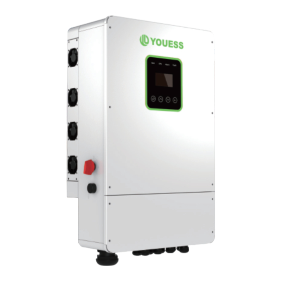
3.3 Work Modes Inverter provides multiple work modes based on different requirements. In addition to the above three basic modes, there is also an “Advanced Mode”. Please refer to Chapter 11 for details. 3.4 Dimension Grid Alarm Fault... - Page 7 Object Description 3.5 Terminals of PV inverter DC switch BAT input Wi-Fi CAN1/CAN2/RS485/BMS485,BMSCAN/CTL1/CTL2/Type-c upgrade PV1~PV4 input Grid Alarm Fault Generator Grid BACK-UP1 output BACK-UP2 output RSD button WARNING ! Qualified electrician will be required for the * Port Function CAN1/CAN2: Communication interface for connecting inverters. RS485: Read the internal data of inverter.
-
Page 8: Technical Parameters
4. Technical Parameters Insulation Resistor Detection Residual Current Monitoring Unit 4.1 Inverter specication Output Over Current Protection Back-up Output Short Protection Terminal temperature detection Technical Data U-5K-L1 U-6K-L1 U-8K-L1 U-10K-L1 Output Over Voltage Protection PV Input Data Output Under Voltage Protection MAX.DC Input Power 7.5kW 12KW... -
Page 9: Packing List
5. Installation site meets the following conditions: Not in direct sunlight. 5.1 Check for Physical Damage Not in areas where highly Flammable materials are stored. Not in potential explosive areas. Make sure the inverter is intact during transportation. If there is any visible damage, such as cracks, please contact your dealer immediately. - Page 10 Space Requirement Step 4: Remove the cover screws by Allen Wrench and remove the c over. Remove the waterproof cover by a flat blade screwdriver. Wiring box conduit plugs, Conduit Position Min. size plugs are provided for 1 inch conduit fittings. If used conduit fitting is not 1 inch, Left 300mm an appropriate conduit adaptor should be used.
-
Page 11: Electrical Connection
6. Electrical Connection 6.2 Grid Connection (GEN connection) 6.1 PV connection Step1. Check the grid voltage. 1.1 Check the grid voltage and compare with the permissive voltage range Hybrid can be connected in series with 4-strings PV modules for 5kW, 6kW, 8kW, (Please refer to technical data). -
Page 12: Back-Up:load1 And Load2 Connection
6.3 Back-up:Load1 and Load2 Connection Note! Inverter has On and Off grid function, the inverter will deliver output power through In case of discrepancies between wiring mode of local policy and the AC port when the grid is on, and it will deliver output power through back-up port operation guide above, especially for the wiring of neutral line, when the the grid is off. -
Page 13: Battery Connection
Requirements for BACK-UP load BMS PIN Definition Waring! Communication interface between inverter and battery is RS485 or CAN with Make sure the BACK-UP load power rating is within BACK-UP output a RJ45 connector. rating, otherwise the inverter will shut down with an “over load” warning. -
Page 14: Wifi Connection (Optional)
6.5 WIFI Connection (optional) 6.7 CT Installation instructions Inverter provides a WIFI port which can collect data from inverter and transmit it to monitoring-website by WIFI. (Purchase the product from supplier if needed) CT is short for“current transform”,is used to detect Grid current . 1) Diagram Note! If CT is not installed or installed reversely, the functions of... -
Page 15: E-Stop Installation
7. LCD Operation 6.8 E-Stop Installation .1 Control Panel The emergency stop (E-stop) button (D) included with this inverter is used to stop the PV modules from passing voltage on the string conductors, leaving them at a safe voltage for first responders to perform work in or on the building. The e-stop button is a normally closed (NC) contact. -
Page 16: Instructions For The Use Of Three Modes
7.3 Instructions for the use of three modes 1. Master MASTEP/SLAVE 1. SELF CONSUME 2. Slave ADDRESS 2. PEAK SHIFT 1. WORK MODE COMMON BAT 3. BATPRIORIANT 2. EPS ENABLE COMMON CT 3. BAT WAKE-UP 14. PARALLEL PHASE A/B/C 4. PV INPUT 1. -
Page 17: Lcd Operation
For example, Before selecting the mode, you can set it up according to the local power grid, PV input mode and battery type. LCD Operation Power grid: Select 1: Set up Press Esc button Press Enter button Circular User 8.1 LCD Interface display interface Default... - Page 18 VpBUS: Real-time voltage of bus capacitor of the machine. DC VOLTAGE VnBUS: Real-time voltage of bus capacitor of the machine. VpBUS: 235.0V LeakCurr: Real-time leak current of the machine. 8.1.5 PV1 Input display interface VnBUS: 235.0A Interface Description LearkCur: PV1 input real-time voltage, current and power. PV1 INPUT VOLT: 0.0V...
- Page 19 FREQ: Grid real-time frequency. INV: 0.00Hz POWER L1: INV-L1 real-time voltage. INV-L1 real-time current. PV I/P: PV power. L1: 0.0V 0.00A PV I/P: L2: INV-L2 real-time voltage. INV-L2 real-time current. BAT: BAT power. L2: 0.0V 0.00A BAT: 8.1.15 LOAD 8.1.20 Temperature Interface Description Interface...
- Page 20 8.2 SETTING 8.2.4 System setting 8.2.1 State 8.2.4.0 System setting Interface Description Interface Description SETUP: Press Enter to user settings interface. USER This interface is used to access system information. INQUIRE: Query machine model, serial number, software version. SYS SETTING 1:SETUP Press Up/Down button to move corresponding options.
- Page 21 8.2.4.2 EPS enable Interface Description WORKTIME* When the Grid and PV are powered off, Enable the battery to 1)The maximum allowable setting time is 24h(one day), It is allowed to set six EPS ENABLE supply power to the load, default option is enable. different charging and discharging states within 24h.(time1 twice,time2 1:DISABLE twice,time3 twice), The inverter runs repeatedly every day according to the set...
- Page 22 Interface Description 8.2.4.7 BUTT ENABLE Interface Description This interface is used to set the lead acid battery discharging BAT END VOLT voltage. (The input value ranges from 40 to 51) When it is set to “ENABLE”, you can power on or power off BUTTON ENABLE INPUT: 045.0...
- Page 23 8.2.6 Grid standard 8.2.7 RUN SETTING 8.2.6.0 Grid std 8.2.7.0 RUN SETTING Interface Description Interface Description This interface is used to select run setting. This interface is used to select Grid standard. SETTING Press Up/Down button to move corresponding options; Press Up/Down button to move corresponding options;...
- Page 24 8.2.7.6 VAC-MIN Interface Description The input value of Grid low voltage. 8.2.7.2 GRID POWER GRID VOLT LOW Interface Description It effects when grid mode choose custom. INPUT: The input value is power percent of grid. GRID PERCENT UNIT: INPUT: 100% 8.2.7.7 VAC-MAX Interface Description...
- Page 25 8.2.7.10 ACTIVE REF. 8.2.10 LANGUAGE SETTING Interface Description ACTIVE Type This interface is used to select active reference. 8.2.10.0 LANGUAGE 1.PWR-VOLT RES Press Up/Down button to move corresponding options; Interface Description 2.PWR-FREQ RES Press Enter button to enter the selected menu. This interface is used to select language.
- Page 26 8.2.14 MAINTENANCE 8.2.14.0 MAINTENANCE 8.2.16.1 NUM Interface Description Interface Description This operation is used to select the number of parallel This interface is used to enter maintenance. PARALLEL NUM PASSWORD machines. INPUT: INPUT: XXXXX 8.2.16.2 MASTEP/SLAVE Interface Description 8.2.15 FCTRY RESET This interface is used for paralleling, and the inverter is Master/Slave selected as the master or slave.
- Page 27 Enable or disable CT sharing. COMMONM CT *Please read Chapter 9 for more details. 1.DISABLE 2.ENABLE 8.2.16.6 PHASE A/B/C Interface Description Interface Description 1. This interface is used to select run setting. This interface is used to select the output phase of the 2.
- Page 28 This interface is used to set the battery charging current Chg Curr to BAT when the generator is used. INPUT: 8.2.17.7 POWER UNIT: Interface Description This interface is used to set the diesel generator power. POWER INPUT: 08.0 UNIT: 8.3 INQUIRE 8.2.17.4 MAX RUN TIME Interface Description...
-
Page 29: Generator Use Operation Guide
Interface Description This interface shows Software version. FIRMWARE ARM: V1.XX.XX DSP: V1.XX.XX Generator Use Operation Guide 8.3.4 RUNNING RECORDS 9.1 Generator Use Diagram Interface Description This interface shows running recodes. REC(01) 1)The Generator is connected to the grid port of the inverter. The connecting 02:Batdisconnect cable shall be covered with CT. - Page 30 2)The Generator is normally connected to the Generator port. The connecting cable between the Generator and the inverter does not need to be 9.2 Generator Operation Notes covered with CT. The connection line of the power grid port should be connected with CT.
- Page 31 Refer to 11.3.2 CONTRL. Inverter Parallel Guide Rated power of Generator. 10.1 Parallel System Diagram Multiple inverters can be installed together to deliver more power. When AC loads are present, all units effectively share the load. The system diagram is as follows.
- Page 32 10.1.2 Parallel connection for 120/208 three phase(American Standard) 10.1. 1 Split phase (120/240Vac) parallel connection diagram CAN1 CAN2 CAN1 CAN2 ①②③ DC Breaker for battery. BMS_CAN/485 ①②③ DC Breaker for battery. BMS_CAN/485 CT2 CT1 CT2 CT1 U-8K-L1: 250A DC breaker. U-8K-L1: 250A DC breaker .
- Page 33 10.1.3 Parallel connection for 230/400 three phase CAN1 CAN2 10.2 Parallel Communication Cable Connection ①②③ DC Breaker for battery. BMS_CAN/485 CT2 CT1 U-8K-L1: 250A DC breaker. ④ AC Breaker for grid port. U-8K-L1: 40A AC breaker. ⑤ AC Breaker for backup. load port.
- Page 34 10.4 Parallel System Setting Advanced Mode Operation Guide The parallel setting page can be visited in the following steps in the screen: USER->1. SETUP->PASSORD CHECK->15.parallel 11.1 Advanced Mode Introduction 10.4.0 Setting Interface Description The hybrid inverter can be programmed to control how and when to use grid power.The This interface shows parallel setting.
- Page 35 time slot grid charge attribute is enabled. 11.2.3 Advan Ctrl Pv Charge Only: If user don’t want to use grid to charge the battery in any time ,please Interface Description enable this attribute. >Global control, whether the power grid can charge the battery. --ADVAN CONTROL-- Bat Charge On Priority :If there will be a storm or other emergency, user can use this 2.->Whether TIME OF USE is enabled...
- Page 36 abnormal (2) Restart the inverter and wait until it functions 12. Fault diagnosis and solutions normally. Grid over vol (3) Contact customer service if error warning continues. The inverter is easy to maintain. When you encounter the following problems, please refer Grid low freq Grid Frequency is (1) Check if the grid is abnormal.
- Page 37 The inverter (1) Cut off all the power of the machine and wait The inverter may be (1) Restart the inverter and wait until it functions Bus Relay Fault temperature is higher one hour, then turn on the power of the damaged normally.
- Page 38 NOTICE: The copy right of this manual belongs to Shenzhen Youess Energy Storage Technology Co., Ltd. Any corporation or individual should not plagiarize, copy, reduction, or distribution this manual in any form or by any means. All rights reserved. The information in this document(including software, etc.)is subject to change without notice.