Table of Contents
Advertisement
Available languages
Available languages
Quick Links
Advertisement
Table of Contents

Related Manuals for Truper MUT-105


Summary of Contents for Truper MUT-105
- Page 1 Multímetro digital Digital multimeter INSTRUCTIVO INSTRUCTIVE 10403 MUT-105 NOTA IMPORTANTE: Este producto no debe quedar expuesto a goteo o salpicaduras por líquidos. IMPORTANT NOTE: This product shall not be exposed to liquids dripping or spatter.
- Page 2 ESPAÑOL 1. INTRODUCCIÓN Este instructivo proporciona toda la información de seguridad, instrucciones de operación, especificaciones y mantenimiento del multímetro, el cual es compacto, portátil y operado con pilas. Este instrumento hace mediciones de tensión c.a. / c.c., corriente c.a. / c.c., resistencia, continuidad audible, diodo, hFE, frecuencia, capacitancia y temperatura, ángulo de permanencia, tacómetro.
- Page 3 Use las terminales, funciones y rango adecuadas a las mediciones No utilice o almacene el multímetro en ambientes de alta temperatura, humedad, donde haya productos explosivos, inflamables y campos magnéticos fuertes. El desempeño del multímetro se puede deteriorar después de mojarse. Cuando use las puntas de prueba mantenga los dedos detrás de las guardas para dedos.
-
Page 4: Características Generales
2. CARACTERÍSTICAS GENERALES Pantalla digital: Cuenta 1 999 y se actualiza 2 veces/seg. Medida LCD: 62 mm x 37 mm Indicación de polaridad: “ - ” Se muestra automáticamente Indicador de sobre rango: Se muestra “OL” Indicador de pila baja: Se muestra “... -
Page 5: Descripción De Partes
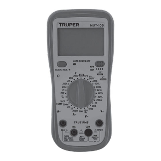
4. DESCRIPCIÓN DE PARTES 1. LCD 2. Botón de retención de datos 3. Luz indicadora 4. Interruptor giratorio / interruptor de funciones 5. Conector de entrada 6. Funda 7. Soporte 8. Cubierta de pilas... -
Page 6: Pantalla Lcd
PANTALLA LCD Ciclo de trabajo seleccionado Modo de apagado automático seleccionado Prueba de grados º Fahrenheit seleccionada Retención de datos habilitado — Prueba de grados c.c. º Celsius seleccionada — Signo negativo Prueba de transistor hFE seleccionada c.a. Prueba de continuidad Pila baja: cambie de inmediato audible seleccionada Símbolo de tacómetro... -
Page 7: Especificaciones
5. ESPECIFICACIONES Se garantiza por 1 año la precisión 23 °C 5 °C menor a 80% HR EXPLICACIÓN TÉCNICA RMS REAL • Para la medición de señal de onda no sinusoidal el método de medición del valor de RMS real es menor al método de respuesta de valor promedio. - Page 8 La velocidad de tacómetro del motor se conoce como velocidad ralentí. La velocidad ralentí del motor se muestra como valor ralentí. ESPECIFICACIONES ELÉCTRICAS TENSIÓN c.c. Rango Resolución Precisión 200 mV 0,1 mV (0,8% de rdg + 5 dgts) 20 V 10 mV (0,8% de rdg + 3 dgts) 200 V...
- Page 9 Medición máxima en caída de tensión: 200 mV Corriente máxima de entrada: 20 A (El tiempo de prueba debe estar entre 10 segundos) Respuesta de frecuencia: (40 ~ 1000) Hz (Para onda sinusoidal estándar y onda triangular) Pantalla: Tru RMS (Sólo como referencia cuando está sobre 200 Hz en otras ondas) CORRIENTE c.a.
- Page 10 CAPACITANCIA (Rango Automático) Rango Resolución Precisión 20 nF – 20 mF Dividido entre (8% de rdg + 5 dgts) 1 000 Protección en sobrecarga: 250 V c.c. y c.a. valor pico. TEMPERATURA Rango Resolución Precisión -40 °C ~ 1 000 °C 1 °C (3% de rdg + 4 dgts) -40 °F ~ 1 832 °F 1 °F...
-
Page 11: Instrucciones De Operación
FRECUENCIA (Rango automático) Rango Precisión 0 ~ 60 MHz (1% + 5) Protección en sobrecarga: 250 V c.c. y c.a. valor pico PRUEBA DE TRABAJO Rango Resolución Precisión 10 - 95% 0,1% (2,0% + 3 dgts) Protección en sobrecarga: 250 V c.c. y c.a. valor pico 6. -
Page 12: Medición De Resistencia
2. En caso que el LCD muestre “OL”, significa que está sobre el rango. Cambie el interruptor de funciones a un rango más alto. MEDICIÓN DE CORRIENTE c.c. • Inserte la punta de prueba negra al conector “COM” y la roja al conector “mA” ... - Page 13 • Coloque el interruptor de funciones en el rango adecuado de resistencia, conecte las puntas de prueba a través de la resistencia que se va a medir. NOTA 1. Si el valor de resistencia medido excede el valor máximo del rango seleccionado, el LCD va a mostrar "OL", por lo tanto, debe poner el interruptor de funciones en un rango mayor.
-
Page 14: Medición De Temperatura
MEDICIÓN DE TEMPERATURA • Coloque el interruptor de funciones en el rango “ºC / ºF”. • Inserte el enchufe negro (o “-“) de la sonda termopar tipo K al conector “COM”, y el enchufe rojo ( o “+”) en el conector“ INPUT ”. •... - Page 15 • Arranque el motor, lea la lectura en la pantalla, divida la lectura entre el número de cilindros, el resultado es la velocidad de giro (tacómetro). 7. APAGADO AUTOMÁTICO Y ENCENDIDO DE LA LUZ LCD • Después de encender, el LCD muestra “APO”, que significa que el multímetro está...
- Page 16 1. El cambio de pila y fusible solo se deben llevar a cabo después que las puntas de prueba estén desconectas y el aparato apagado. 2. Afloje los tornillos con un desarmador adecuado y retire la parte baja de la carcasa. 3.
- Page 17 ENGLISH 1. 1. INTRODUCTION This Instructive provides all the safety information, operation instructions, specifications and maintenance of the multimeter which is compact, portable and battery operated. This instrument measures AC / DC voltage measurements, AC / DC current, resistance, audible continuity, diode, hFE, frequency, capacitance and temperature, permanence angle, tachometer.
- Page 18 Do not use or store the multimeter in environments with high temperature, humidity, where there are explosive and flammable products, and strong magnetic fields. The multimeter performance can be deteriorated after getting wet. When using the test probes keep your fingers behind the finger guard. Disconnect the feed circuit and discharge all the capacitors from the voltage before measuring resistance, continuity, diodes o hFE.
-
Page 19: General Characteristics
2. GENERAL CHARACTERISTICS Digital display: Counts 1 999. Updates 2 tomes / second LCD measure: 62 mm x 37 mm Polarity indicator: “- “is shown automatically Over range indicator: Shows “OL “ Low battery indicator: It shows Battery characteristics: 9 V DC 6F22 carbon-zinc battery included Range selector: Auto or manual Operation temperature:... -
Page 20: Parts Description
4. PARTS DESCRIPTION 1. LCD 2. Data retention button 3. Indicator light 4. Rotary switch / function switch 5. Inlet connector 6. Sleeve 7. Support 8. Batteries cover... -
Page 21: Lcd Display
LCD DISPLAY APO Automatic power off mode Work cycle selected ºF Fahrenheit degrees test selected Data retention enabled Celsius degrees test selected ºC hFE transistor test selected Negative sign Continuity test selected Diode test selected Low battery: replace immediately Auto range mode selected AUTO Continuance Angle symbol... -
Page 22: Specifications
5. SPECIFICATIONS One (1) year warranty in accuracy 23 ºC 5 ºC lower than 80% HR. RMS REAL TECHNICAL EXPLANATION • To measure the non-sine wave signal, the measure method of the real RMS value is lower than the average value response method. •... - Page 23 ELECTRIC SPECIFICATIONS DC VOLTAGE Range Resolution Precision 200 mV 0,1 mV (0,8% de rdg + 5 dgts) 20 V 10 mV (0,8% de rdg + 3 dgts) 200 V 100 mV 1 000 V (1% de rdg + 5 dgts) Input resistance: 5 M in mV range Other ranges: 5 M Overload protection: 250 V DC or maximum value of AC...
- Page 24 Maximum measurement in voltage drop: 200 mV Input maximum current: 20 A (The test time shall be between 10 seconds). Frequency response: (40 – 1 000) Hz (for standard sine wave and triangular wave) Display: Real RMS (only as reference when is over 200 Hz in other waves) AC CURRENT Range Resolution...
- Page 25 CAPACITANCE (automatic range) Range Resolution Precision 20 nF – 20 mF divided by (8% de rdg + 5 dgts) 1 000 Overload protection: 250 V DC and AC peak value TEMPERATURE Range Resolution Precision -40 °C ~ 1 000 °C 1 °C (3% de rdg + 4 dgts) -40 °F ~ 1 832 °F 1 °F...
-
Page 26: Voltage Measurement
hFE TRANSISTOR TEST (connect the adapter) Range Corriente de prueba Tensión de prueba Ib 2 µA PNP & NPN 0 ~ 1000 Vce 1 V FREQUENCY (automatic range) Range Precision 0 ~ 60 MHz (1% + 5) Overload protection: 250 V DC and AC peak value WORK TEST Range Resolution... -
Page 27: Measuring Dc Current
NOTE 1. If the measured current is unknown beforehand, set the functions switch in the highest range. Then, switch into the adequate range according to the value shown. 2. If the LCD shows “OL”, means it is above range. Switch the functions switch into a higher range. -
Page 28: Diode And Continuity Test
• Set the functions switch into the adequate resistance range. Connect the test probes through the resistance to be measured. NOTE 1. If the resistance value measured exceed the maximum value of the selected range, the LCD will show “OL”. Therefore, set the functions switch in a higher range. - Page 29 MEASUREMENT OF TEMPERATURE • Set the functions switch into “ºC / ºF” range. • Insert the black plug (o “-“) of the type K thermocouple probe into connector “COM” and the red plug (o “+”) into the “INPUT” connector. • Carefully, touch with one end of the thermocouple probe the object to measure.
-
Page 30: Fuse And Battery Replacement
• Start the motor. Read the display reading. Divide the reading between the number of cylinders. The result is the turn speed. (tachometer). 7. AUTOMATIC SHUT OFF AND TURNING ON THE LCD LIGHT • After being turned on, the LCD shows “APO”, meaning the multimeter in in automatic power off mode. - Page 31 Disconnect the test probes before opening the batteries back cover. 1. Changing battery and fuse shall only be carried out after the test probes are disconnected and the device id off. 2. Using the right screwdriver, loosen the screws and remove the lower part of the housing.
- Page 32 Truper ® Para hacer efectiva la garantía presente el producto, póliza sellada o factura o recibo o comprobante, en el establecimiento donde lo compró...
Need help?
Do you have a question about the MUT-105 and is the answer not in the manual?
Questions and answers