
Summary of Contents for MSTRONIC PSE-904R
- Page 1 PSE-904R/908R/912R Power Source Equipment (Power over Ethernet Hub) USER’S MANUAL MSTRONIC CO., LTD.
-
Page 2: Table Of Contents
User’s Manual MSE PSE-904R/908R/912R Contents 1. Introduction................Features....................Package Contents................. 2. Hardware Description............Physical Dimension................Front Panel.................... LED Indicators..................Rear Panel.................... Power On....................Network Application................RJ-45 Remote Control Port..............3. Software Utility Installation..........4. GUI Management..............Display and Illustration................System Login.................. -
Page 3: Introduction
PSE shuts down the power to that port. Devices that are not equipped to receive power over Ethernet may require an external splitter in order to be powered. Contact Mstronic for such a splitter. -
Page 4: Package Contents
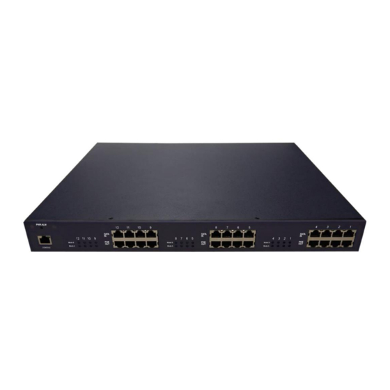
This Section mainly describes the hardware of the MSE PSE-904R/908R/912R and gives a physical and functional overview. Physical Dimension MSE PSE-904R/908R/912R physical dimension is: 430mm x 407mm x 44mm (Lx W x H),1U, 19” or 23” Rack mountable. Front Panel Figure 2-1. -
Page 5: Led Indicators
User’s Manual MSE PSE-904R/908R/912R LED Indicators The LED Indicators gives real-time information of systematic operation status. The following table provides descriptions of LED status and their meaning. Status Color Description A network device is detected(10/100/1000 Mbps) Green but no communication activity is... -
Page 6: Rear Panel
Rear Panel The AC inlet, DC input terminal, and 4 Ventilation fan are located at the rear panel of the MSE PSE-904R/908R/912R. The device will work with AC in the range 100-240V AC, 50-60Hz. Or work with DC 48V. (42~57VDC) Power On Connect the power cord to the power socket on the rear panel of the PSE. -
Page 7: Remote Control Port
Internet Explorer or Mozila, to set the TCP/IP parameter. Before you use the web interface to set the PoE TCP/IP, verify that PSE-904R/908R/912R is properly installed on your network and PC on the network can access PoE via the web-browser. - Page 8 9. Key in ID (user name) and password to enter PoE TCP/IP parameter setting. Default ID and password is admin and system. 10. PSE-904R/908R/912R TCP/IP parameter has 4 pages interface (administrator setting, TCP Mode, UDP Mode and UART). You must change the administrator, TCP/IP mode &...
- Page 9 User’s Manual MSE PSE-904R/908R/912R 11. Administrator setting: you can assign nickname, IP setting, user name, password and view system information. Nickname: You can assign a name to the device. IP Address: You must assign the IP address reserved by your network. The default IP is 192.168.1.10.
- Page 10 User’s Manual MSE PSE-904R/908R/912R 12. TCP Mode: You can update the TCP control parameter here. Telnet Server/Client: Set to Server for PoE management operation. Port Number: You can assign port number for TCP/IP operation. The default Port Number is 23.
- Page 11 User’s Manual MSE PSE-904R/908R/912R 13. UDP Mode: This mode is not used in the PoE application. MSTRONIC CO., LTD.
- Page 12 User’s Manual MSE PSE-904R/908R/912R 14. UART: You must set UART Control to RS232,9600,8,N,1 for PoE operation. Mode: Set to RS232 for PoE operation. Baud rate: Set to 9600 bps for PoE operation. Character Bits: Set to 8 bits for PoE operation.
- Page 13 User’s Manual MSE PSE-904R/908R/912R 15. When you have configured your set up, you must reset the device to take effect. MSTRONIC CO., LTD.
-
Page 14: Software Utility Installation
User’s Manual MSE PSE-904R/908R/912R 3. Software Utility Installation Before you start to remote configuring PD, please install the software utility. Through the software utility, you can easily to control the PD that connect with PoE and view the PD parameter information. The software utility provides GUI interface and user can easily to start with it. -
Page 15: Gui Management
User’s Manual MSE PSE-904R/908R/912R 4. GUI Management Display and Illustration Connect the PSE with a PC through the remote control port. Then, run the software utility (Netclient). You will see the main utility interface below. Tools bar PSE station selection & alarm indicator Display PSE station PSE station name&IP setting... -
Page 16: System Login
User’s Manual MSE PSE-904R/908R/912R System Login Run the management software, the system will show the diagram below. Now enter the password, first enter the default setting which is “0000” MSTRONIC CO., LTD. -
Page 17: Modify Password
User’s Manual MSE PSE-904R/908R/912R Modify Password Click “File” and select “Modify PSW”, you can modify the password, the system permits 3 sets of password. MSTRONIC CO., LTD. -
Page 18: Edit Station Tcp/Ip
User’s Manual MSE PSE-904R/908R/912R Edit Station TCP/IP Click “Setting”, and select “LAN Setting”, or click “LAN Setting” icon, the screen will enter IP Setting window. The port Mode A LED indicates pair 12/36 power status. The port Mode B LED indicates pair 45/78 power status. - Page 19 User’s Manual MSE PSE-904R/908R/912R In the IP Setting display window, you can edit the station name, TCP/IP address and port number. Click the Edit icon to modify this parameter. In the Edit window, click the View icon to display TCP/IP parameter.
-
Page 20: Edit Remote Poe Ip
User’s Manual MSE PSE-904R/908R/912R Edit Remote PoE IP In the IP Setting display window, you can use “PoE IP Setting” icon to start the web-browser. To modify the remote PoE TCP/IP parameter, please reference RJ-45 Remote Control Port of section 2 Hardware Description (page 8). -
Page 21: Gui Connect All
User’s Manual MSE PSE-904R/908R/912R GUI Connect All In the main page window, click “GUI” and select “Connect All” command or click “connect all” icon, if the Station Selection window shows the name icon and displays power status(green or red) light, it means that the PSE connection is correct. You can then select station to configure you PSE. - Page 22 User’s Manual MSE PSE-904R/908R/912R GUI connect example: In the Station Selection window, the LED indicates real time connection of PSE. Green-----this connection and PSE power are normal. Red--------this connection is OK but PSE power is not correct. Orange---this connection is not working..
-
Page 23: Single Station Connect/Disconnect
User’s Manual MSE PSE-904R/908R/912R Single Station Connect/Disconnect In the IP Setting window, you can click Connect/Disconnect icon to enable/disable single station connection, the LED indicates real time status of TCP/IP. Green-----TCP/IP connection is OK. Red--------TCP/IP connection is not working. Gray-------TCP/IP parameter is not setting. -
Page 24: Station And Status Window Select
User’s Manual MSE PSE-904R/908R/912R Station and Status Window Select The PSE management software can monitor 24 PSE simultaneously. In the GUI Disconnect All mode, only the TCP/IP Status display window can be used to set the TCP/IP parameter. In the GUI Connector All mode, there two display windows can choose - Port Status &... -
Page 25: Edit Port Name
User’s Manual MSE PSE-904R/908R/912R Edit Port Name Click “Setting”, and select “PoE Name” or click the “PoE Name” icon. The screen will enter IP Setting window. You can assign a name to the PSE port individually. In the “Module Select” window, select the suitable port that you require. -
Page 26: Configuration
User’s Manual MSE PSE-904R/908R/912R Configuration . In the main page window, click “Config”, and select “Setup”, the screen will show the system control panel as below. Set icon: Apply the operation mode to PSE system. Set Enable/Set Disable icon: Change the Board Status window to set enable/disable. -
Page 27: Factory Setting
User’s Manual MSE PSE-904R/908R/912R Factory Setting Click “Config”, and select “Factory” or click the “Factory” icon. The screen will show the factory setting control panel as below: then click “Y” for the Factory Setting. MSTRONIC CO., LTD. - Page 28 User’s Manual MSE PSE-904R/908R/912R Factory setting as below: Operation Mode → Auto (Auto, Force & Shutdown) AC Disconnect → Off(On & Off) DC Disconnect → On (On & Off), default setting. MSTRONIC CO., LTD.
-
Page 29: Board Status
User’s Manual MSE PSE-904R/908R/912R Board Status Click “Config”, and select “GetBoardStatus”, or click “Board STATUS” icon, the screen will show current status of each port. MSTRONIC CO., LTD. -
Page 30: Port Status
User’s Manual MSE PSE-904R/908R/912R Port Status In the main page window, click “StatusDisp”, and select “PortStatus”, or click the “PORT STATUS” icon, the screen will show current status of each port and current power supply status of each module. If all power modules are working normally, the “Sys. Power” will show a green light, if any module has failed, the light will turn to red. -
Page 31: Gui Version
User’s Manual MSE PSE-904R/908R/912R GUI Version Click “StatusDisp”, and select “GUI Version”, the screen will show the version of the EMS utility MSTRONIC CO., LTD. -
Page 32: Gui Disconnect All
User’s Manual MSE PSE-904R/908R/912R GUI Disconnect All Click the “GUI”, and select “Disconnect All”, or click the “GUI disconnect all” icon to disconnect the communication between GUI and PSE. MSTRONIC CO., LTD. -
Page 33: File Open And Save
User’s Manual MSE PSE-904R/908R/912R File Open and Save You may click “File” and select “Open”, or click the ”Open file” icon, to open the previous setting file. Click “Save”, or “Save file” icon, to save the current setting. MSTRONIC CO., LTD. -
Page 34: Technical Specification
User’s Manual MSE PSE-904R/908R/912R 5. Technical Specification PARAMETER PSE-904R PSE-908R PSE-912R Data Ports PoE Ports Console Port 1× RJ45 console interface for management Per port DC 55V@1636mA, the maximum power of two Output power adjacent ports is 150W when AC input.
Need help?
Do you have a question about the PSE-904R and is the answer not in the manual?
Questions and answers