
Summary of Contents for SITEK SlickDevice S1
- Page 1 SlickDevice™ S1/F1 Intelligent SRD Controller Owner'sManual SITEK Process Solutions www.sitekprocess.com 916-797-9000 233 Technology Way, Bldg. 3 Rocklin, CA 95765 Cover Page 1 Page 1 © SITEK Process Solutions...
-
Page 2: Table Of Contents
Process Complete Unsuccessfull ..........................26 Alarms..................................27 How to clear alarms..............................30 Maintenance Mode / Tool Down ...........................31 Error codes ................................32 Error Codes List...............................33 N2 Saver: Customized Nitrogen Parameters ......................35 Autocycle ..................................37 Manual Mode ................................39 Lamp test ................................41 Page 2 © SITEK Process Solutions... - Page 3 Resistivity Probe working properly........................73 Resistivity Probe not connected.........................74 All Manual Operation .............................75 Manual Mode Security Interlocks list........................77 Analytics ..................................78 Logbook ..................................79 How to download SITEK SlickDevice™ log information onto your laptop..............83 Program Installation: ..............................83 USB Cable: ................................83 Page 3 © SITEK Process Solutions...
- Page 4 Operation: ................................84 Download file: ................................89 Page 4 © SITEK Process Solutions...
-
Page 5: Introduction
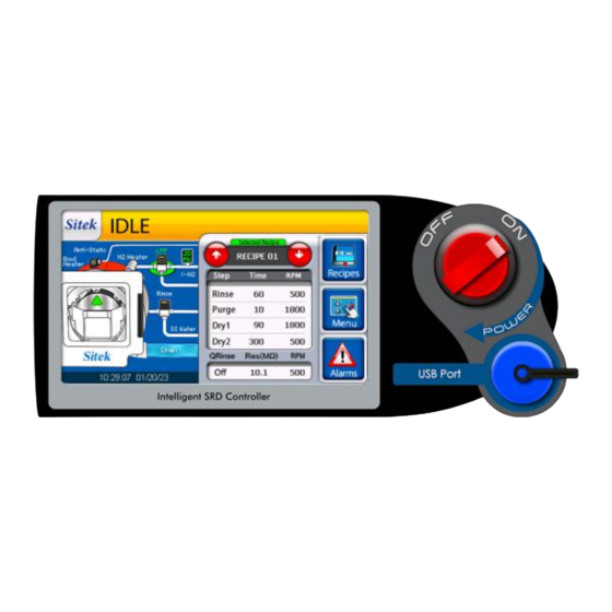
Introduction The S1 and F1 models of SITEK's SlickDevice™ are the first intelligent replacement controllers for the Semitool Spin Rinse Dryer. SlickDevice™ uses intelligent automation and control algorithms for smooth and safe tool operation using a clear and easy-to-read interface showing the process in real-time. -
Page 6: Layout
The S1 Model of the SlickDevice™ is a highly efficient controller designed to operate with SRDs that feature Brushless DC Motors and Servo Amps. The SlickDevice™ F1 Model is specifically engineered to operate with SRDs that have brushed DC motors and DC motor controllers. Page 6 © SITEK Process Solutions... - Page 7 • 50 pin ribbon cable RPJ2 connector • Ground cable • All connectors match existing Semitool 101 or 102 controllers. ** Replacement to a 102 controller requires an adapter to account for an alternate pin format. Page 7 © SITEK Process Solutions...
-
Page 8: Process Description
• 6 total recipe capacity: • 5 process recipes • 1 auto cycles • Data logging and analytics • Safe Manual Mode operation with alarm diagnostics • N2 waste reduction • Heated or ambient N2 process configuration Page 8 © SITEK Process Solutions... -
Page 9: Initial Start Up
4 numbers combination. The password can be changed later in the Settings section of the controller. The controller is now ready for the initial run. Note: The controller will self-calibrate to the motor controller and motor. Page 9 © SITEK Process Solutions... -
Page 10: General Settings
Adjustment of general settings (Clock, Brightness, Volume and Password). When the Idle screen appears, Press “Menu”. Enter the password that was set on initial startup Select “Controller Settings” from the Main Menu page 1 of 2. Page 10 © SITEK Process Solutions... -
Page 11: Clock Setting
Select “Clock” from the Settings page. To set the time, use the up/down arrows under “H,M,S” in “Set Time”. To set the date, use the up/down arrows under “Set Date”. Save settings and press “back to menu”. Page 11 © SITEK Process Solutions... -
Page 12: Screen Brightness And Volume
Select “Brightness” or “Volume” from the Settings page. Move the slider to set the “Screen Brightness” or “Beep Volume”. Touch default to set the default value for Screen Brightness/Volume. The default value corresponds to recommended SITEK setting. Page 12 © SITEK Process Solutions... -
Page 13: Change Password
To change the password, you must first enter the current password, then enter and confirm the new password. Use “ENTER” to move to the next field. ** Forgot password? Contact SITEK for password reset procedure. Page 13 © SITEK Process Solutions... -
Page 14: Recipe Program Settings
Use the numeric pad on the right to enter numeric data. Use Clear to delete a current value inside of a field. You can navigate to each cell using “ENTER” or by tapping on it directly. Page 14 © SITEK Process Solutions... - Page 15 If an incorrect entry is made, use the "Delete" button to re-enter a new value. Selecting "Cancel" or leaving the recipe prior to saving will disregard all changes. Page 15 © SITEK Process Solutions...
- Page 16 When completed, select "Save" to capture the changes. Verify the new values once the display has refreshed. Return to the main process screen via "Back to process". Page 16 © SITEK Process Solutions...
-
Page 17: Quality Rinse
If this timer concludes, the controller will alarm. Quality Rinse time can be adjusted using + or – symbols. Available range from zero to 3600 Seconds. Page 17 © SITEK Process Solutions... -
Page 18: Skip Step Or Dry Only Recipe
Eliminator can be adjusted for each recipe. You can also use the “Process Settings” button on the top of the screen for the same function. NOTE: Save the recipe by pressing “Save” before selecting Process Settings. Page 18 © SITEK Process Solutions... - Page 19 If the tool does not include a Static Eliminator, turning the Anti- Static eliminator off will remove any alarm related to this option. This example shows how to set the process to deactivate "Anti-Static" for Recipe 04 during Dry1 and Dry2 cycles. Page 19 © SITEK Process Solutions...
-
Page 20: Process Setting Example
Static is simple. After selecting "RECIPE 04", touch every option to activate "Yes" or "No". Running the Recipe Bowl Heater Off Anti-Static N2 Valve N2 Heater This is a recipe running according to the previous process settings selections. Page 20 © SITEK Process Solutions... -
Page 21: Quick Reference Of Operations Screens
SlickDevice™ Intelligent SRD controller checks all parameters before starting the process. Should a required parameter or sensor state not meet the initial conditions, the screen will show a message detailing the condition preventing the tool from starting. Page 21 © SITEK Process Solutions... -
Page 22: Rinse
Purge: Once the 3-second delay is over, the Purge and N2 valve opens to purge the residual DI Water from the DI manifold. The valve’s current state and N2 flow are shown on the screen’s left side. Page 22 © SITEK Process Solutions... -
Page 23: Dry1
The heaters' amperage value is shown, and the corresponding color- matching state appears on the heaters' mimic. In this example an N2 Heater fail is shown on Valves and Actuators tab. Page 23 © SITEK Process Solutions... -
Page 24: Dry2
The maximum Q-Rinse time is 3600 seconds. An alarm will display if the tool cannot reach the resistivity setpoint within the specified time. Page 24 © SITEK Process Solutions... -
Page 25: Process Complete Successful
If the SRD is equipped with a light Indicator or a light tower, the blue color lamp will be on indicating a successful run is complete and the operator can remove the cassette from the STOP button for chamber. top SRD Page 25 © SITEK Process Solutions... -
Page 26: Process Complete Unsuccessfull
SRD Controller returns to the Idle State, and a circle with a number appears next to the Alarms icon on the Idle Screen showing how many error messages were found during the unsuccessful run. Page 26 © SITEK Process Solutions... -
Page 27: Alarms
Alarms The Alarms Screen can be accessed from the main Operator Screen. Alarms can also be accessed through Main Menu – Page 1 of 2. Page 27 © SITEK Process Solutions... - Page 28 The Alarm Screen of the F1 model differs slightly because of its DC motor type, which doesn't have a servo amp and an internal fuse. Every time an alarm is present, the corresponding Light Indicator flashes in red color Page 28 © SITEK Process Solutions...
- Page 29 Servo Amp Fuse Fuse failure inside controller Contact Sitek for controller recalibration and repair. Open I nside Check if a Resistivity probe is connected to the back of the Running a Qrinse recipe without a controller.
-
Page 30: How To Clear Alarms
Touch the illuminated alarm icon to acknowledge and clear the alarm. The alarm icon will turn off. If the condition persists after returning to the Idle Screen, the alarm will light again and repeat until the issue is fixed. Page 30 © SITEK Process Solutions... -
Page 31: Maintenance Mode / Tool Down
Idle Screen showing the current tool state. The tool still can run and operate all functions in this state so troubleshooting can proceed, however this state is intended for maintenance personal only. Page 31 © SITEK Process Solutions... -
Page 32: Error Codes
Error Code = R42. It starts with the letter R meaning it was a Running error. Screen showing ERROR CODE R42: UNCOMPLETED RUN OF RECIPE: N2 PRESSURE FAILED WHILE RUNNING A RECIPE “Process aborted, N2 pressure failure detected while running a recipe" Page 32 © SITEK Process Solutions... -
Page 33: Error Codes List
"-- Rotor up failure. Rotor is not up." ERROR CODE: S34 CLEAR ALARMS “Please clear all alarms before starting." ERROR CODE: M41 DOOR WAS OPENED WHILE RUNNING IN MANUAL MODE “Door was opened while motor was spinning during Manual Operation" Page 33 © SITEK Process Solutions... - Page 34 End or error codes list. Note: Please be aware that the Error Code S30 - CHECK SERVO AMP FUSE INSIDE SLICKDEVICE™ SRD CONTROLLER "Check Servo Amp fuse inside SlickDevice™ controller" does not apply to the SlickDevice™ F1 Model. Page 34 © SITEK Process Solutions...
-
Page 35: N2 Saver: Customized Nitrogen Parameters
The N2 Heater cool down will provide N2 flow post dry cycle process to dissipate heat and extend heater life. Slide the switch to the left as illustrated to enable. Page 35 © SITEK Process Solutions... - Page 36 N2 Saver feature. A label on top of the screen indicates when N2 saving is on. The blue base ring color for the N2 valve and upper “N2 Saver activated” banner indicate when the N2 saver is active. Page 36 © SITEK Process Solutions...
-
Page 37: Autocycle
Autocycle and select the hours between each run, go to the main menu and use the down arrow to go to Main Menu – page 2 of 2. Select Autocycle to enter the Autocycle settings page. Page 37 © SITEK Process Solutions... - Page 38 Autocycle is shown in the top right section of the screen. If a recipe is run, the timer will restart once the recipe is complete. This is true for whether an ordinary recipe or Autocycle recipe is run. Page 38 © SITEK Process Solutions...
-
Page 39: Manual Mode
SlickDevice™ SRD Controller. To operate Manual Mode, select “Menu” on Idle Screen. Then select “Manual Mode” on Main Menu Page 1 of 2. Page 39 © SITEK Process Solutions... - Page 40 Heaters, Resistivity Cell, Lamps, and test Sensors without running a specific process or recipe. The Manual Mode screen of the F1 model shows a brushed DC motor. The functionalities explained are applicable to both the S1 and F1 models. Page 40 © SITEK Process Solutions...
-
Page 41: Lamp Test
The screen shows the valves available inside the SRD and how they are connected. Select the corresponding valve icon to actuate the valve solenoid. Some actions cannot be executed simultaneously, see Valve Security Interlocks on next page. Page 41 © SITEK Process Solutions... -
Page 42: Valve Security Interlocks
However, a potential problem could arise because the Purge valve is already open. The system detects this condition and shows a warning message. Security Interlocks have been programmed to avoid hazardous conditions. Never bypass Security Interlocks Page 42 © SITEK Process Solutions... - Page 43 After testing the valve Actuator, go back to Manual Mode pressing the arrow on the top left corner of the screen. SlickDevice™ sets the valves back to default settings upon returning to the Manual Mode screen. Page 43 © SITEK Process Solutions...
-
Page 44: Sensors Test F
Blanket Heater Process Switch, so the Bowl Heater is automatically turned on. AC Electrical current is provided to the Bowl Heater during the sensors test. AC Current measure is shown on the screen. The Blanket Heater could be HOT! Page 44 © SITEK Process Solutions... -
Page 45: How To Check The Sensors
AC Electrical Current measured in Amps Blanket Heater Process Switch state Using this built-in tool, maintenance personnel does not need to remove SRD side panels and use a multimeter or clamp meter to determine heater statuses. Page 45 © SITEK Process Solutions... -
Page 46: Start And Stop Button Test
(This is a sensor test only; the SRD will not start by pressing the START button while using this Sensor test.) The START and STOP button detection is confirmed by a checkmark next to each button on the screen. Page 46 © SITEK Process Solutions... -
Page 47: Sensors Check List
Blanket Heater Process Switch reaches the pre-set sensor temperature, then the SlickDevice™ controller checks the corresponding check mark. If the process switch fails, the blanket heater temperature reaches the Overtemp Switch pre-set value and cuts out the AC to the heater. Page 47 © SITEK Process Solutions... -
Page 48: Actuators
SRD in the field to reach the electric circuits inside and use different types of meters for testing. To select the oscilloscope-style built- in tool go to Manual Mode and select “Actuators”. The following image shows the main parts of the actuator screen. Page 48 © SITEK Process Solutions... -
Page 49: Actuators - Anti-Static
Actuators – Anti-Static SlickDevice™ uses a SITEK proprietary algorithm called DDL to detect the correct operation of the static eliminator. An internal sensor detects a pulsing current, and the corresponding readings are plotted in a graphic in the display area. -
Page 50: Anti-Static Unit Failing
Anti-Static unit failing SlickDevice™ detects a failing Anti-Static unit through a SITEK proprietary DDL algorithm. This algorithm analyzes the samples to calculate a value indicating the functionality of the Static eliminator under test. A failing static eliminator is different from a normally operating static eliminator and the SlickDevice™ can detect this difference using the DDL algorithm. -
Page 51: Anti-Static Unit Not Connected
Actuator Screen for Anti-Static will show a circuit open icon on the Circuit Status window. The Pass/Fail area shows “Fail” Total number of samples Anti-Static circuit open Readings and average plotted values are zero or near zero Maximum reading was 4 FAIL: This unit failed DDL test Page 51 © SITEK Process Solutions... -
Page 52: Actuators - N2 Heater
Only the heaters can be tested simultaneously; the Anti-Static test does not work simultaneously with heater test. To start the N2 Heater circuit test, make sure the Anti-Static option is turned off as only heaters can be tested simultaneously. Page 52 © SITEK Process Solutions... -
Page 53: N2 Heater Working Properly
N2 Heater current N2 Heater circuit plot in yellow color closed Channel 1: N2 Heater in yellow. Channel 2: Not activated AC current starts to flow into the circuit AC current values appear here Page 53 © SITEK Process Solutions... -
Page 54: N2 Heater Failing
N2 flow into the chamber. If any of these parts fail, the circuit test fails. Typically, an AC current of zero represents this type of N2 Heater circuit failure. Channel selected Empty display area (Failure) N2 Heater circuit is open (Failure) N2 Heater circuit readings are N2 pressure zero (Failure) available Page 54 © SITEK Process Solutions... -
Page 55: N2 Heater Security Interlock
The N2 Heater circuit test can only be performed if the proper N2 supply is available during the test. SlickDevice™ rejects N2 Heater activation Warning Message Required N2 pressure not available Page 55 © SITEK Process Solutions... -
Page 56: Actuators - Bowl Heater
Anti-Static option is turned off. The Bowl Heater circuit test can also be started while an N2 circuit test is running. Both N2 Heater and Bowl Heater circuit tests can be performed simultaneously. Page 56 © SITEK Process Solutions... -
Page 57: Bowl Heater Working Properly
Type of measure selected selected Processed samples N2 Heater circuit closed Bowl Heater Channel 1: circuit closed N2 Heater in yellow. Process Switch closed. Channel 2: Bowl Heater in red. Channel 2 readings Channel 1 readings Page 57 © SITEK Process Solutions... -
Page 58: Bowl Heater Failing
All this is evidence of a faulty Bowl Heater Circuit. Bowl Heater Circuit activated by user AC Current plot line is flat at zero amps. Bowl Heater Circuit remains open AC Current reading is Zero Amps Page 58 © SITEK Process Solutions... -
Page 59: Bowl Heater Process Switch
1–2 minutes, the process switch opens, indicating the heater temperature is at least 160F; this can be seen on the bottom left portion of the screen. Bowl Heater circuit closed Process Switch open. Page 59 © SITEK Process Solutions... -
Page 60: Bowl Heater Overtemp Switch
AC opened by the current falls to zero Overtemp Switch when (Circuit is open) temperature reaches 230F Process Switch is open (Temperature is above 160F) AC Current reading is Zero Amps Page 60 © SITEK Process Solutions... -
Page 61: Motor And Tach - Manual Mode
Exceeding maximum rotor speed can damage the SRD, destroy substrates, and cause serious injuries or death. The maximum rotor speed and maximum wafers load is usually engraved in the front portion of each rotor. Page 61 © SITEK Process Solutions... -
Page 62: Motor/Tach Manual Mode For S1 Model
Mode screen to test the SRD Brushless Motor and the Tachometer sensor. The SlickDevice™ provides a built-in tool to test the motor and tachometer operation. The motor test can be run in Open Speed Loop or Closed Speed loop. Page 62 © SITEK Process Solutions... -
Page 63: Motor/Tach Manual Mode For F1 Model
DC motor and the Tachometer sensor. The SlickDevice™ provides a built-in tool to test the motor and tachometer operation. The motor test can be run in “Open Speed Loop” or “Closed Speed Loop” using the internal motor driver. Page 63 © SITEK Process Solutions... -
Page 64: Open Speed Loop
F1 model has a "Brush Motor Manual Operation" label and a “DC Motor Driver” image. The explanations provided for the S1 model also apply to the F1 model, and we will use the S1 model images for reference. Page 64 © SITEK Process Solutions... - Page 65 50 RPM each time. Keep the “Up” or “Down” button pressed to speed up the navigation between higher and lower speed values. Page 65 © SITEK Process Solutions...
- Page 66 Please remember: In Open Speed loop mode, the current speed is unlikely to Positioner is deactivated to release the rotor before the motor starts. exactly match the set speed since the controller is not correcting RPM to match. Page 66 © SITEK Process Solutions...
- Page 67 To stop the motor test, press the red “Motor Stop” button. The user can also stop the motor test using the red STOP button on the SRD. Page 67 © SITEK Process Solutions...
-
Page 68: Closed Speed Loop
Both parts work together to detect the motor rotational speed and are known as the tachometer. Once the motor operation is verified using the Open Speed Loop the next step is to test the Closed Speed Loop. Page 68 © SITEK Process Solutions... - Page 69 “STOP”. Use this same button to stop the motor test. The motor is now ramping up to the selected speed and the Closed Speed Algorithm adjusts the speed to the indicated setpoint. Page 69 © SITEK Process Solutions...
- Page 70 Selecting "Back to Menu" while the motor is running stops the motor, activates the brake, and waits until the motor is completely stopped before letting the user select any other option. Page 70 © SITEK Process Solutions...
- Page 71 When the user ends the Motor test by selecting "Back to Menu", the system does not allow another option until the motor is completely stopped and the Door Seal releases. Page 71 © SITEK Process Solutions...
-
Page 72: Resistivity Probe Test
Conductivity is the inverse of Resistivity The Rinse solenoid valve can be opened using the “Open Rinse Valve” button to introduce DI water into the chamber. Page 72 © SITEK Process Solutions... -
Page 73: Resistivity Probe Working Properly
The resistivity probe screen shows the probe temperature, the Resistivity Raw value, and the Corrected Resistivity value. The Corrected Resistivity value corresponds to the temperature compensated Resistivity. This is also the value used by the Quality Rinse cycle. Page 73 © SITEK Process Solutions... -
Page 74: Resistivity Probe Not Connected
Water into the chamber and wait for one minute. If the "No resistivity Cell Detected' is still on top of the screen after one minute, the system indicates a Resistivity Probe is not present. Page 74 © SITEK Process Solutions... -
Page 75: All Manual Operation
Rotor Stop Positioner, N2 Pressure Sensor, a Heaters control area, a Brushless Motor manual speed control, the current Resistivity value, and water temperature all in one single screen. Water temperature Resistivity N2 Pressure Actuators and AC current value Door Brushless Motor Control Solenoid valves Page 75 © SITEK Process Solutions... - Page 76 In this example the user is about to turn on the N2 Heater using manual control The security interlock prevents turning On the N2 Heater without any N2 pressure flowing through the heater first. Page 76 © SITEK Process Solutions...
-
Page 77: Manual Mode Security Interlocks List
Door seal can not be actuated while Warning 109 All Manual door is open. Rinse valve can not be actuated until Resistivity Warning 131 door is closed. Table 2. Security Interlocks in Manual Mode Page 77 © SITEK Process Solutions... -
Page 78: Analytics
All analytics information is saved in permanent memory and cannot be modified. Analytics is where the quantified, historical data is stored, and failure records are captured for tracking purposes and analysis. To access the SRD analytics information, go to Main Menu – Page 1 of 2 and select “Analytics” Page 78 © SITEK Process Solutions... -
Page 79: Logbook
SlickDevice™ keeps a detailed Logbook with more than 125 different events to be recorded. The event's history in the tool is collected for future reference and sorted by date and time. The logbook is stored in Page 79 © SITEK Process Solutions... - Page 80 The Logbook information can be downloaded to a PC or Laptop in plain text format or Excel (CSV file), using a proprietary software. The download process is covered in the next chapter of this manual. Page 80 © SITEK Process Solutions...
- Page 81 The selected date’s logbook number of pages is displayed on top of the screen. Every event is time stamped and is shown in ascending order from the oldest to most recent event. Page 81 © SITEK Process Solutions...
- Page 82 To navigate to the most recent event, select “Bottom” To go up or down one page use the up or down arrow. To go back select “Back to Menu” Page 82 © SITEK Process Solutions...
-
Page 83: How To Download Sitek Slickdevice™ Log Information Onto Your Laptop
2. Create a new folder using any folder name, for example, “SlickDevice™ S1 Support Program". 3. Copy all the SITEK provided files to the folder. You do not need to run an installer to get this ready on your laptop - just copy the files into the new folder. - Page 84 Operation: Before running the SITEK SRD Remote Support software, you must turn on the SlickDevice™ and go to “Menu”. After entering the PASSWORD (default password is 0000, however, your current password may have been changed by a user) you will see the “Main Menu - Page 1 of 2“...
- Page 85 Now, your tool is ready to download log files. The next step is to run the SITEK Remote Support program on your laptop. Go to the recently installed folder and open the program “Manufacturer Remote Support.exe” This will open the Remote Support program Page 85 ©...
- Page 86 Select the COM port connected to the SITEK SlickDevice™ SRD Controller and then click on “Connect to SlickDevice”. The correct COM port should automatically populate. You can now see the information about the SRD controller: Page 86 © SITEK Process Solutions...
- Page 87 To see a list of the log files inside the SITEK SRD Controller, click on “Log File List” Page 87 © SITEK Process Solutions...
- Page 88 You can now see a list showing all the log files inside the SITEK SRD Controller. The Log File List should look like this: Page 88 © SITEK Process Solutions...
- Page 89 To download a copy of any of the log files you must first select the file format you want for the downloaded file and you can select between “Text File .txt” or “Excel File .csv” format. (Default value is “Text File.txt”) Page 89 © SITEK Process Solutions...
- Page 90 Then, using “Enter log date”, confirm the month, day and year corresponding to the file to be downloaded and hit ENTER on the keyboard. In this example the selected file is for date 04/14/20. Page 90 © SITEK Process Solutions...
- Page 91 Select the desired file location on your laptop and click on “Save”. Page 91 © SITEK Process Solutions...
- Page 92 After the selected file is downloaded you can see the "File transfer complete!” indication. Page 92 © SITEK Process Solutions...
- Page 93 Thank you for using the SITEK SlickDevice™ controller and reviewing our manual! We hope you enjoy our product. For any other questions or comments, please contact SITEK directly. You can reach us through our website or phone. SITEK Process Solutions www.sitekprocess.com...
Need help?
Do you have a question about the SlickDevice S1 and is the answer not in the manual?
Questions and answers