IPhotonix 7261G, 7262G, 7263G, 7267G, 7268G, 7269G Quick Install Manual
- Quick install manual (2 pages)
Advertisement
OVERVIEW
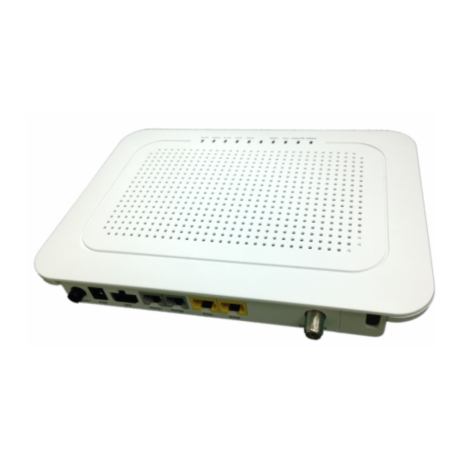
The 72xx SFU residential ONT delivers high quality VoIP voice service, Ethernet data service for high-speed internet access and IPTV broadcast video plus video on demand services. They provide the following user features: (see Model List for exact features)
- 2 POTS ports - voice telephone service
- 2 LAN ports - Ethernet connectivity
- WiFi port - WiFi connectivity
- CATV port - CATV, Return and HPNA services
- USB port - data backups service
- UPS port - UPS service
INSTALLATION
The 72xx SFU ONT can be mounted vertically or horizontally on any flat surface.
Unpack
Unpack the unit and verify that it is free from shipping damage.:

Desk Mount
- Set the unit on a flat surface considering the following:
- within reach of the power source
- no thermal obstructions
- not in direct sunlight
- user ability to monitor/operate the unit
Wall Mount
- Use wall anchors or wood screws (if mounting to plywood mounted on a wall), spaced 5.709" apart center to center for horizontal mounting or 3.543" apart center to center for vertical mounting.
Fiber Connection
- On the back left side of the unit is fiber cover. Slide it off as shown.

- With the fiber connector exposed, remove thedust plug, clean the fiber ends and terminate the SC equipped fiber.
![]()
Exposure to invisible LASER radiation may cause serious retinal damage or even blindness. Verify the optical source is disabled through the use of an optical power meter before handling optical fibers.

- Insert the fiber into the cover slot and slide thecover back onto the 72xx unit.


DC Power Input
Connect the 2.1mm DC power plug to the port labeled PWR.

UPS Power and Alarms

The UPS power/alarm input uses a MOLEX 43025-0800 connector. Pin orientation as shown is viewed from the rear.

| PIN | NAME | ALM |
| 1 | Power Input (+12 VDC) | – |
| 2 | UPS Status: On Battery | 1 |
| 3 | UPS Status: Battery Missing | 2 |
| 4 | Signal Return | – |
| 5 | Power 12V Return | – |
| 6 | UPS Status: Replace Battery | 3 |
| 7 | UPS Status: Low Battery | 4 |
| 8 | No Connection (N/A) | – |
Pins for the connector are Molex 46235-5002
 NOTICE: Please use UL certified UPS which meets Limited Power Source standard.
POTS Connections
Connect up to 2 phones to the unit. There are 2 pots, labeled POTS1 and POTS2.

LAN Connections
Connect the computers/routers to the ports labeled ETH1 or ETH2.

CATV Connection
Connect the Television or Set Top Box to the port labeled Coax Network. This port also supports Return Service on select models.

HPNA Connection
Connect the coaxial cable to the port labled
Coax Network, using a splitter to connect to the same port with CATV.

WiFi Connection
Change the notebook/computer WiFi network SSID to "iphotonix-ONTxxxx". This may be changed manually.
USB Connection
Connect a flash-disk/portable hard disk to the port labeled USB on the left side of the units.

User Controls
The 72xx SFU ONT is equipped with an ON/OFF button. User functionality should be limited to this button.

LED Descriptions
The 72xx SFU ONT has visual LED indicators to help the user determine the operational state of the unit. The LEDs are defined as follows:
Power
| ON | Unit is powered on |
| OFF | Unit is powered off |
Battery
| ON | Battery is charged and unit is operating normally on external power. |
| Flashing Slow | Unit is running off of battery power only. Check power supply to unit. |
| Flashing Fast | Battery is low and unit may turn off if external power is not restored. |
| OFF | Battery is missing or defective. |
FAIL
| ON | Indicates Loss Of Signal (LOS). No optical signal is present. |
| Flashing Slow | Marginal signal indicates a weak optical signal from carrier. Clean fiber connection per local practice and check power with an optical meter. |
| Flashing Fast | Software upgrade is in progress. |
| OFF | Optical signal is present and operating normally. |
HPNA
| ON | HPNA link active |
| OFF | No HPNA link active |
ETH 1- 2
| ON | Ethernet link is operational. |
| Flashing | Indicates data transmission / reception. |
| OFF | No Ethernet link or port is not provisioned and connected. |
POTS
| ON | Line is off hook (call active or in process) |
| Flashing Slow | Indicates ringing line. |
| OFF | Line is on hook (no call in process) or port is not provisioned. |
MGMT
| ON | Management channel (OMCI) is active |
| OFF | Management channel (OMCI) is not active. |
WLAN
| ON | WiFi function is active |
| Flashing | Indicates active data TX/RX |
| OFF | WiFi function is not active |
Environmental Requirements
| Rated Voltage: | DC 12V |
| Rated Current: | 2A |
| Operating Temperature: | +5°C to +40°C |
| Operating Relative Humidity: | 5% to 85% |
| Storage Temperature: | -40°C to +60°C |
| Storage Relative Humidity: | 0% to 95% |
Model List
| Model | Functions | Select |
| 7261G | 2POTS+2GE+HPNA | |
| 7262G | 2POTS+2GE+HPNA+WiFi | |
| 7263G | 2POTS+2GE+HPNA+CATV | |
| 7267G | 2POTS+2GE+HPNA+CATV+Return | |
| 7268G | 2POTS+2GE+HPNA+CATV+WiFi | |
| 7269G | 2POTS+2GE+HPNA+CATV+Return+WiFi |

Documents / ResourcesDownload manual
Here you can download full pdf version of manual, it may contain additional safety instructions, warranty information, FCC rules, etc.
Download IPhotonix 7261G, 7262G, 7263G, 7267G, 7268G, 7269G Quick Install Manual
Advertisement

Need help?
Do you have a question about the 7261G and is the answer not in the manual?
Questions and answers