Table of Contents
Advertisement
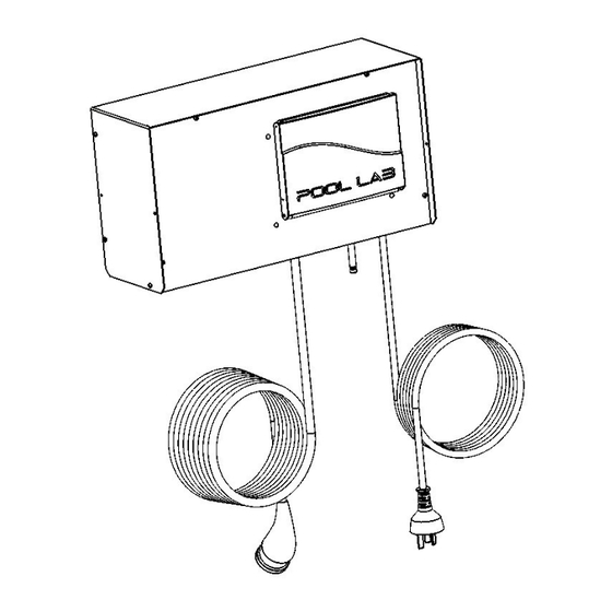
OWNER'S MANUAL
PL Series Automatic Chlorinator
Patented Technology
Patent Technology Numbers:
Australia No. 2004245133
Canada No. 2528374
Europe No. 04736187.8
New Zealand No. 544430
USA No. 7,658,842
IMPORTANT
Read this manual carefully before operating your Pool Lab Automatic Chlorinator
PL25, PL35, PL45 Ideal Salinity@ 25 ºC
3000ppm
ABSOLUTE MAXIMUM SALINITY 6000ppm @ 25ºC
KEEP THIS MANUAL IN A SAFE PLACE FOR FUTURE REFERENCE
Manufactured by Poolpower Australia Pty Ltd
Factory 1b, 39-45 Susan Street
ELTHAM, VICTORIA, AUSTRALIA 3095
email:
service@poolpower.com.au
rev. 8
Advertisement
Table of Contents

Related Manuals for POOL LAB PL35


Summary of Contents for POOL LAB PL35
- Page 1 Europe No. 04736187.8 New Zealand No. 544430 USA No. 7,658,842 IMPORTANT Read this manual carefully before operating your Pool Lab Automatic Chlorinator PL25, PL35, PL45 Ideal Salinity@ 25 ºC 3000ppm ABSOLUTE MAXIMUM SALINITY 6000ppm @ 25ºC KEEP THIS MANUAL IN A SAFE PLACE FOR FUTURE REFERENCE...
-
Page 2: Important Safety Instructions
• Use only original Pool Lab replacement cells with identical model numbers. • Follow all aspects of local and national Electrical Codes when installing Pool Lab • equipment. For outdoor pools, chlorine residuals can be protected from destruction from the •... -
Page 3: Table Of Contents
Table of Contents IMPORTANT SAFETY INSTRUCTIONS................2 Health and Hypothermia Warnings......................2 GENERAL PRECAUTIONS....................4 ELECTROLYTIC CELL PRECAUTIONS................4 INTRODUCTION........................5 CELL MAINTENANCE......................6 TO REMOVE & INSPECT THE ELECTRODE..................... 6 CLEANING THE ELECTRODE – CALCIUM SCALE...................7 INSTALLING THE ELECTRODE......................... 7 CONTROL PANEL OVERVIEW.....................8 SETTING THE TIME AND DATE...................9 SETTING ON / OFF TIMERS....................9 SPECIAL FEATURES......................10 USER AUTHORITY LEVEL........................ -
Page 4: General Precautions
Unnecessarily high salt levels may contribute to corrosion of pool and spa • equipment. Pool Lab recommend the use of Cyanuric Acid (Stabilizer) at a concentration • of between 50-80 ppm for outdoor pools to help protect chlorine in the water... -
Page 5: Introduction
Water loss due to evaporation does not cause any loss of salt. All Pool Lab models contain digital time clocks with two programmable ON/OFF periods available for fully automatic operation of your pump &... -
Page 6: Cell Maintenance
CELL MAINTENANCE Where calcium levels are below 200ppm, the mineral content is low and the water is correctly balanced, little or no maintenance to the cell is normally required. The automatic reversing of the electrode polarity will be sufficient to dissolve the calcium scale formed. Periodic inspections must however be made to ensure scale and or debris is not forming or building up on the electrodes within the cell. -
Page 7: Cleaning The Electrode - Calcium Scale
CLEANING THE ELECTRODE – CALCIUM SCALE You will need hydrochloric acid (33%), and a plastic container or bucket deep enough to stand the electrode vertically in with the electrode plates fully submerged. The container or bucket should be preferably not too broad, as this will require a larger amount of acid. A standard 10 Litre bucket is usually acceptable. -
Page 8: Control Panel Overview
CONTROL PANEL OVERVIEW LCD DISPLAY – The display has three top level views, and a menu system: HOME – Displays running mode and chlorinator output. TIME/DATE – Displays current time and date TIMER – Displays filtration ON / OFF times MAIN MENU –... -
Page 9: Setting The Time And Date
SETTING THE TIME AND DATE Time is displayed in 24 hour format. 00:00 is midnight, 12:00 is midday. Date is displayed in day / month / year format. Setting the correct date will allow the system to automatically adjust for daylight savings time. -
Page 10: Special Features
SPECIAL FEATURES USER AUTHORITY LEVEL To prevent accidental changes to critical settings, the Pool Lab PL Series incorporates a user authority level. By default the authority level is set to USER. Before any critical settings can be edited, the user authority level must be raised to INSTALLER. There is also a LIMITED level which prevents adjustment of all settings, and there are also TECHNICIAN and FACTORY levels which require a PIN. -
Page 11: Recovery Mode
RECOVERY MODE (included in software revision CLR-P24F-253 and above) Recovery mode will run the filtration system and chlorinator for the amount of time set in SETTINGS - RECOVERY (default setting is 24 hours), then revert back to AUTO filtration mode. This may be useful when additional filtration and/or chlorination is required after periods of heavy use, or when cleaning / preparing a pool for the swimming season. -
Page 12: Hydrogen Gas Safety
HYDROGEN GAS SAFETY You may take comfort from the fact that the Pool Lab Cell has worldwide patents on its design relating to safety. Pool Lab has the worlds safest Cell Your Pool Lab Chlorinator must be installed in accordance with the installation instructions listed in this manual. -
Page 13: Diagnostic Messages
DIAGNOSTIC MESSAGES Diagnostic messages will be displayed on the bottom line of the LCD when in HOME VIEW. The messages and their meanings are explained below, with some basic tips to rectify the issue if necessary. If the problem persists, consult the troubleshooting guide for more information. -
Page 14: Pump Protection Active
PUMP PROTECTION ACTIVE The system has detected a low flow condition for longer than the time specified in the PUMP PROTECTION TIME setting. The pump has been turned off, and will not restart until the filtration mode is changed manually. –... -
Page 15: Chlorine Producton And Control
CHLORINE PRODUCTON AND CONTROL FREE CHLORINE LEVEL A free chlorine residual of 1.0ppm to 3.0ppm must be maintained in the pool / spa water at all times. The ability of the chlorine generator to maintain this level will alter with respect to the chlorine demand imposed by bather load and environmental factors. -
Page 16: Water Balance
With a salt chlorinator, it is essential to have approximately the correct amount of salt in the water to achieve the conductivity required for the chlorine cell to work efficiently. Pool Lab recommend using regular pool salt (Sodium Chloride). -
Page 17: Chlorine Stabilizer - Cyanuric Acid
“chlorine smell” most noticeable around heavily used indoor pools. As a general rule Pool Lab recommend shock dosing your pool with liquid chlorine at least once every swim season as this can significantly reduce chlorine demand and greatly improves the disinfecting power of the free chlorine in the water. -
Page 18: High Calcium (Hard) Water Sources - The Langlier Saturation Index
High Calcium (Hard) water sources – the Langlier Saturation Index The Langlier Saturation Index (Si) is a relationship between the Calcium Hardness, Total Alkalinity, pH and water temperature. When the water is balanced correctly, the Si value should be somewhere between -0.2 and +0.2. A value lower than -0.2 indicates the water is corrosive, and a value higher than +0.2 indicates the water is scaling. -
Page 19: Water Circulation
– usually the skimmer box. This place will be most representative of the readings acquired by the Pool Lab ASP. Also ensure the displayed results are up-to-date by initiating a water test via the ASP... -
Page 20: Installation
INSTALLATION PLUMBING Cell Installation The Cell housing must be installed vertically with the inlet and discharge plumbing positioned such that the water enters and exits the cell chamber at the lowest point of the vertical cell. 50mm pipe must be plumbed directly onto both ends of the cell with the water flowing in the direction as indicated by the arrow on the cell housing. -
Page 21: Plumbing Example
Plumbing Example Air Blower Installation – If an air blower is installed and connected directly to venturi spa jets, then a vented loop must be installed. This allows any potential build up of hydrogen gas to escape from the blower line before it comes in contact with the blower motor. NOTE: The top of the loop must be above the maximum water level in the spa. -
Page 22: Power Supply And Controller
USE ONLY IDENTICAL REPLACEMENT PARTS WHEN SERVICING. THIRD PARTY EQUIPMENT CONTROLLERS When a Pool Lab salt chlorinator is installed on a system with a third party equipment controller that is in control of the filtration pump, please setup as described below. -
Page 23: Salt
SALT ONLY USE APPROVED POOL GRADE SALT THAT IS SPECIFICALLY LABELLED • FOR SWIMMING POOL AND SPA USE SALT MUST BE GREATER THAN 99% PURE • DO NOT USE ROCK SALT, SALT WITH YELLOW PRUSSIATE OF SODA, SALT • WITH ANTI-CAKING ADDITIVES OR IODIZED SALT. ADD SALT TO POOL WATER AS FAR AWAY FROM THE FILTRATION SYSTEM •... -
Page 24: Salt Addition Tables
SALT ADDITION TABLES The Ideal Salinity Level for Pool Lab Salt Chlorinator models PL25, PL35 and PL45 (including Plus and MAX models) is 3000ppm. Use the table below to calculate the amount of salt required to bring your water to the ideal salinity level. -
Page 25: Troubleshooting
TROUBLESHOOTING SYMPTOM / POSSIBLE CAUSES POSSIBLE SOLUTIONS DISPLAY MESSAGE No Display No Power Check for power at socket External Timer An external timer (if fitted) may not be providing power Internal Fuse Return unit for servicing Unit resetting, or power An excessively high salt level Check salt level in water. - Page 26 SYMPTOM / POSSIBLE CAUSES POSSIBLE SOLUTIONS DISPLAY MESSAGE Display Message: Salt level too low Check salt level and add salt if required. “CHECK SALT” Temperature too low When water temperature is below 25ºC the cell may not be able to produce at 100%. Calcified or blocked cell.
- Page 27 For all models, cell voltage should be close to 24.0V (+/- 1.0 V) For PL25, cell amps should be between 2.08A – 6.0A For PL35, cell amps should be between 2.91A – 9.0A For PL45, cell amps should be between 3.75A – 12A During normal operation the cell will cycle ON and OFF over a 3 minute duty cycle to maintain the correct chlorine output (as measured in grams per hour).
-
Page 28: Warranty Information
Where used for a purpose other than described in this manual – Use of non-genuine components – Use of chemicals or optional equipment not authorised for use by Pool Lab – Where immediate action has not been taken to rectify a problem –... - Page 29 NOTES...
Need help?
Do you have a question about the PL35 and is the answer not in the manual?
Questions and answers
Have a pool lab Pl35 and getting a message "Check Salt level'. The salt level ha sbeen test and is 3448 ppm and I **** clean the cell and now looks ok and no debris or scale. still getting the message. The system is still producing cholrine
The ideal salinity level for the POOL LAB PL35 is 3000 ppm. If the salt level is 3448 ppm and the cell is clean, the "Check Salt Level" message may be triggered due to a worn-out cell. The manual suggests that if the salt level and water temperature are normal and the cell is clean, this message may indicate that the cell needs to be checked and possibly replaced.
This answer is automatically generated