
Related Manuals for Eneo AK-21

Summary of Contents for Eneo AK-21
- Page 1 Quick Installation Guide AK-21 Accessory part for eneo products Learn more about eneo IN series on our YouTube channel.
-
Page 3: Table Of Contents
TABLE OF CONTENT SAFETY INSTRUCTIONS �������������������������������������������������������������������������������������������������������� 4 General ������������������������������������������������������������������������������������������������������������������������������������������������������������������������������������������4 Product specific �������������������������������������������������������������������������������������������������������������������������������������������������������������������������5 WEEE (Waste Electronical & Electronic Equipment) �����������������������������������������������������������������������������������������������������6 Graphical Symbols ��������������������������������������������������������������������������������������������������������������������������������������������������������������������6 PRIOR TO USE �������������������������������������������������������������������������������������������������������������������������7 Dimensions (in mm) & Specifications ��������������������������������������������������������������������������������������������������������������������������������7 Parts supplied �����������������������������������������������������������������������������������������������������������������������������������������������������������������������������7 INSTALLATION ������������������������������������������������������������������������������������������������������������������������8 Ceiling Mounting ����������������������������������������������������������������������������������������������������������������������������������������������������������������������8 Wall Mounting ����������������������������������������������������������������������������������������������������������������������������������������������������������������������������8 Mounting Holes �������������������������������������������������������������������������������������������������������������������������������������������������������������������������9... -
Page 4: Safety Instructions
SAFETY INSTRUCTIONS General • Before switching on and operating the system, first read this safety advice and the operating instructions� • Keep the operating instructions in a safe place for later use� • Installation, commissioning and maintenance of the system may only be carried out by authorised individu- als and in accordance with the installation instructions - ensuring that all applicable standards and guidelines are followed�... -
Page 6: Weee (Waste Electronical & Electronic Equipment)
WEEE (Waste Electronical & Electronic Equipment) Correct Disposal of This Product (Applicable in the European Union and other European countries with separate collection systems)� This marking shown on the product or its literature, indicates that it should not be disposed with other household wastes at the end of its working life�... -
Page 7: Prior To Use
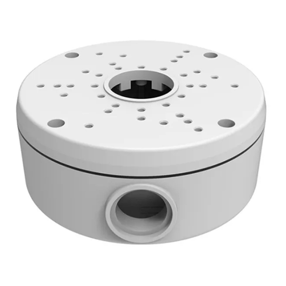
PRIOR TO USE • Install the mount onto a strong structure such as concrete wall • Use the supplied accessories when installing the mount bracket depends on mounting position Dimensions (in mm) & Specifications Construction: Aluminum Cast Dimensions(mm): Ø 134,30 x 56,50 Weight: 396,00 g (0�87 lb) Parts supplied... -
Page 8: Installation
INSTALLATION Ceiling Mounting 1� Use the mounting template to drill the necessary holes in the correct position in the ceiling� 2� Hammer the four expansion crews into the holes� 3� Feed the power and BNC cables through the box� 4� Secure the box with the four screws� 5�... -
Page 9: Mounting Holes
Mounting Holes 1-4: not needed Use these holes for mounting the Mounting the INB-5xx / INB-6xx Bullet Camera Base diameter: Ø 84,00 mm Use these holes for mounting the Mounting the MED-55F0036MOA Turret Camera Base diameter: Ø 90 mm 7-8: not needed Use these holes for mounting the Mounting the INB-7xx Bullet Camera Base diameter: Ø... - Page 11 INHALTSVERZEICHNIS SICHERHEITSHINWEISE �������������������������������������������������������������������������������������������������������12 Allgemein ���������������������������������������������������������������������������������������������������������������������������������������������������������������������������������� 12 Produktspezifisch ������������������������������������������������������������������������������������������������������������������������������������������������������������������� 13 WEEE-Richtlinie (Elektro- und Elektronik-Altgeräte) ������������������������������������������������������������������������������������������������� 14 Grafische Symbole ����������������������������������������������������������������������������������������������������������������������������������������������������������������� 14 VOR DEM GEBRAUCH ����������������������������������������������������������������������������������������������������������15 Abmessungen (in mm) & Spezifikationen ��������������������������������������������������������������������������������������������������������������������� 15 Lieferumfang ��������������������������������������������������������������������������������������������������������������������������������������������������������������������������� 15 INSTALLATION ����������������������������������������������������������������������������������������������������������������������16 Deckenmontage ��������������������������������������������������������������������������������������������������������������������������������������������������������������������� 16 Wandmontage ������������������������������������������������������������������������������������������������������������������������������������������������������������������������ 16 Montagelöcher������������������������������������������������������������������������������������������������������������������������������������������������������������������������...
-
Page 12: Sicherheitshinweise
SICHERHEITSHINWEISE Allgemein • Bevor Sie das System anschließen und in Betrieb nehmen, lesen Sie zuerst diese Sicherheitshinweise und die Betriebsanleitung� • Bewahren Sie die Betriebsanleitung sorgfältig zur späteren Verwendung auf� • Montage, Inbetriebnahme und Wartung des Systems darf nur durch dafür autorisierte Personen vorgenom- men und entsprechend den Installationsanweisungen - unter Beachtung aller mitgeltenden Normen und Richtlinien - durchgeführt werden�... -
Page 14: Weee-Richtlinie (Elektro- Und Elektronik-Altgeräte)
WEEE-Richtlinie (Elektro- und Elektronik-Altgeräte) Ordnungsgemäße Entsorgung dieses Produkts (Gilt für die Europäische Union und die anderen Europäischen Länder mit getrennten Sammelsystemen) Dieses am Produkt oder in seiner Dokumentation gezeigte Symbol bedeutet, dass es am Ende seiner Lebensdauer nicht mit dem Hausmüll entsorgt werden darf� Um eventuelle Umwelt- oder Gesund- heitsschäden durch unkontrollierte Abfallbeseitigung zu verhindern, dieses Gerät von anderen Ab- fallarten trennen und ordnungsgemäß... -
Page 15: Vor Dem Gebrauch
VOR DEM GEBRAUCH • Die Anschlussbox an einer tragfähigen Struktur wie z� B� einer Betonwand befestigen� • Verwenden Sie bei der Montage der Halterung je nach Montageposition das mitgelief- erte Zubehör� Abmessungen (in mm) & Spezifikationen Ausführung: Aluminiumguss Abmessungen(mm): Ø 134,30 x 56,50 Gewicht: 396,00 g Lieferumfang... -
Page 16: Installation
INSTALLATION Deckenmontage 1� Nutzen Sie die Bohrschablone um die notwendigen Löcher an der richtigen Position in der Decke zu bohren� 2� Hämmern Sie die vier Dübel in die Bohrlöcher� 3� Führen Sie die Strom- und BNC-Kabel durch die Box� 4� Befestigen Sie die Dose mit den vier Schrauben� 5�... -
Page 17: Montagelöcher
Montagelöcher 1-4: wird nicht benötigt Verwenden Sie diese Löcher für die Montage der INB-5xx / INB-6xx Bullet Kamera Basisdurchmesser: Ø 84,00 mm Verwenden Sie diese Löcher für die Montage der MED-55F0036MOA Turret Kamera Basisdurchmesser: Ø 90 mm 7-8: wird nicht benötigt Verwenden Sie diese Löcher für die Montage der INB-7xx Bullet Kamera Basisdurchmesser: Ø... - Page 20 Videor E. Hartig GmbH Exclusive distribution through specialised trade channels only. Videor E. Hartig GmbH Carl-Zeiss-Straße 8 63322 Rödermark / Germany Tel. +49 (0) 6074 / 888-0 Technical changes reserved Fax +49 (0) 6074 / 888-100 www.videor.com...
Need help?
Do you have a question about the AK-21 and is the answer not in the manual?
Questions and answers