Table of Contents

Summary of Contents for HSE HB 73-5157
- Page 1 Masterflex L/S Digital Pump Drive with Centrifugal pump head User´s manual Ordering number: 73-5157 PUMP DRIVE FOR CENTRIFUGAL PUMP HEAD AP40 (73-5173), 115 - 230 VAC Masterflex L/S Digital Pump Drive with Centrifugal pump head...
-
Page 2: Table Of Contents
Contence 1.0 Warranty ............................3 1.1 Out of Warranty Service ........................4 1.2 Repair Facilities and Parts ......................... 4 1.3 Safety Information ..........................4 1.4 Use Proper Input Plug........................4 1.5 Make Proper Connections ......................... 4 1.6 Observe All Terminal Ratings ......................4 1.8 Avoid Exposed Circuitry ........................ -
Page 3: Warranty
Hugo Sachs Elektronik (HSE) warranties the PUMP DRIVE FOR CENTRIFUGAL PUMP HEAD for a period of one year from the date of purchase. At its option, HSE will repair or replace the unit if it is found to be defective as to workmanship or materials. -
Page 4: Out Of Warranty Service
HSE technicians. 1.2 Repair Facilities and Parts HSE stocks replacement and repair parts. When ordering, please describe parts as completely as possible, preferably using our part numbers. If practical, enclose a sample photo or drawing. -
Page 5: Place Product In Proper Environment
1.11 Place Product in Proper Environment Review the operating manual for guidelines for proper operating environments. 1.12 Observe all Warning Labels on Product CAUTION Refer to manual. Read all labels on product to ensure proper usage. 1.13 Caution Notice CAUTION: FOR RESEARCH USE ONLY. NOT FOR CLINICAL USE ON PATIENTS. The unit itself does not generate waste but may be used with samples that are hazardous. -
Page 6: Introduction
2.0 Introduction These Operating Instructions describe the function and the use of the Masterflex L/S pump drive with coupling to a centrifugal pump head. This manual is just an addition to the Masterflex pump drive manual which describes the functions and the handling of the AP40 pump head. The Masterflex pump drive manual can be found on the USB-stick delivered with the pump drive. -
Page 7: Range Of Application And Safety Precautions
2.2 Range of application and safety precautions The pumps are intended for liquid handling in laboratory and industry. We assume that all laboratory guidelines are observed as well as the recommendations given below: • The electrical circuit between supply and pump must be grounded, use only grounded power cables •... -
Page 8: List Of Items Supplied
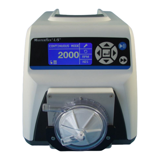
2.4 List of items supplied • Masterflex L/S pump drive with mounted magnetic coupling for AP40 head • mains supply cable • Operating Instructions Accessory if ordered: • AP40 pump head (73-5173) Please check the packaging and the contents for transport damage. If you find any signs of a damage please contact the supplier immediately. - Page 9 Rear side of the unit External input connector 25 pol sub-D, female Fig. 3 Supply socket for mains cable Main Power Switch Supply voltage Supply voltage: 115 / 240 V AC 50/60 Hz Fuse: 3.15A, 250V Supply socket / mains supply cable Use only the original cable supplied.
-
Page 10: Starting Up Overview
3.1 Starting up Overview (see also step by step setup on page 12, this may be easier) Before starting up, setup the pump as described below in steps Use only the CONTINUOUS MODEs “LOCAL” or the “REMOTE CONTROL” mode. Enter key Fig. - Page 11 If you are in REMOTE MODE and attach a voltage to the input you see the RPM number displayed. To start the pump press the blue Start/STOP key. Key Pad Lock : Pressing the ENTER key on this icon goes to the Keypad Lockout screen.
- Page 12 3.2 Step by Step example to do the pump settings: Fig. 6 NAVIGATION: In the Main Menu chose the CONTINUOUS MODE menu. Mode Display: Shows the current operating mode in which the drive will operate. Pressing ENTER key when highlighted will cycle through the different operation modes. Use always only the CONTINUOUS MODE together with the centrifugal pump head.
- Page 13 Navigate Cursor one step down to SOUNDS Fig. 8 Select Sounds and press ENTER, set Keypad BEEP to ON and navigate cursor one step down Set BATCH COMPLETE to OFF, navigate cursor to EXIT and press ENTER Navigate Cursor one step down to REMOTE CONTROL and press ENTER Fig.
-
Page 14: Filling Pump Head Bubble Free
Now fill the pump head with liquid. The pump head must not be running dry • Fit tubing and connect to the system • If necessary, secure the tubing with tubing clips or cable ties against slipping off. Not necessary on a well fitting tubing •... - Page 15 3.4 Starting the Pump It is assumed that at this point you have already pre-programmed the PUMP in LOCAL or REMOTE DIRECT MODE In both modes you first have to press the blue start button to start the pump Fig. 11 If you are in LOCAL CONTINUOS MODE the speed can be altered while the pump is running by changing the displayed RPM.
-
Page 16: Application Example: Controlling The Centrifugal Pump By Plugsys Scp Module I.o. To Perform A Constant Pressure Perfusion
4.0 Application example: Controlling the Centrifugal Pump by PLUGSYS SCP module i.o. to perform a constant pressure perfusion In this application the Centrifugal Pump is used to perform a constant pressure perfusion i.o. to perfuse an isolated organ under constant pressure conditions. The perfusion pressure is measured by using an APT300 pressure transducer connected to a TAM-D amplifier. -
Page 17: Analog Interface Connector
5.0 Analog interface connector see original pump drive manual No internal adjustment necessary All setting run via the keys on the display 6.0 Centrifugal pump head The pump head described below is especially designed for pumping blood or erythrocyte suspensions. The AP40 (Medtronic) head can be directly clipped into the holder of the pump drive. -
Page 18: Output Characteristic Of An Ap40 Pump Head
6.1 Output characteristic of an AP40 pump head Diagram 1 shows the flow-pressure characteristic of the combination Masterflex L/S pump drive with pump head AP40 at varying speed settings. At each speed a particular pressure was produced by squeezing the tubing and the flow was measured. -
Page 19: Fitting And Removing The Ap40 Pump Head
6.2 Fitting and removing the AP40 pump head When fitting or removing the pump head the pump drive must be switched off! The baseplate of the pump head is inserted from above into the slot between magnet box and the black pressure plate and pushed down up to the stop. - Page 20 Fig. 16 Rotate the head so that the locking pin engages with one of the recesses Fig.17 Head fixed, pin in the recess Masterflex L/S Digital Pump Drive with Centrifugal pump head...
- Page 21 Fig. 18 To remove the head, tilt it slightly forward and then pull it upwards out of the holder. Masterflex L/S Digital Pump Drive with Centrifugal pump head...
-
Page 22: Operating Notes
7.0 Operating notes Before switch-on Ensure that the pump head is filled with the liquid to be pumped before you switch on. Operating the pump head dry may damage the rotor bearing. Pumping against pressure The maximum flow rate depends on the back pressure (see Diagram 1, chapter 6.1). Speed setting In order to keep haemolysis low you should not set a higher speed than necessary. -
Page 23: Maintenance And Cleaning
8.0 Maintenance and cleaning The pump drive does not require any special maintenance. Any dirt on the housing should be removed immediately. A cloth moistened with water should be used for cleaning. With strongly adhering dirt you can add a little cleaning solution (domestic detergent) to the water. WARNING: •...
Need help?
Do you have a question about the HB 73-5157 and is the answer not in the manual?
Questions and answers