
Summary of Contents for Tork GAP 30
- Page 1 GAP 30 Gas Alarm Control Panel USER MANUEL JANUARY 2022 PLEASE READ THE INSTRUCTION BEFORE USE...
-
Page 2: Table Of Contents
2.4. Front of the device ..............................2.5. Buttons, Leds and their functions ......................2.6. Back of the device ..............................2.7. Terminal and connection points ......................... 2.8. Technicial Features ............................. 2.9. Technical Dimensions ............................SMS-TORK Endüstriyel Otomasyon Ürünleri San. Tic. Ltd. Şti. - Page 3 3. Transport, Storage, Packaging, Warranty and Protection measures ........3.1. Transport ..................................3.2. Storage ................................... 3.3. Packaging ..................................3.4. Guarantee ..................................3.5. Protection measures ............................4. Control Parameters ............................... 4.1. Possible malfunctions and solutions......................4.2. splash screen ................................4.3. Monitoring Screens and explanations ....................4.4.
-
Page 4: Safety Instructions
This warning personal injury. should be heeded. SMS-TORK Endüstriyel Otomasyon Ürünleri San. Tic. Ltd. Şti. -
Page 5: Considerations
1.3. Considerations Pay attention to the following points in order to use the device COUTION safely. • The device should not be used for any other purpose. • Liquid materials should not be placed on the device. • In case of liquid spillage on the device, it should be checked by the authorized company or sent to the technical service. -
Page 6: References And Symbols
Relay outputs port common contact terminal Relay outputs port common contact terminal Relay outputs port common contact terminal Grounding symbol The connection point where the grounding connection of the device will be made. Table 1: Symbols SMS-TORK Endüstriyel Otomasyon Ürünleri San. Tic. Ltd. Şti. -
Page 7: Identity
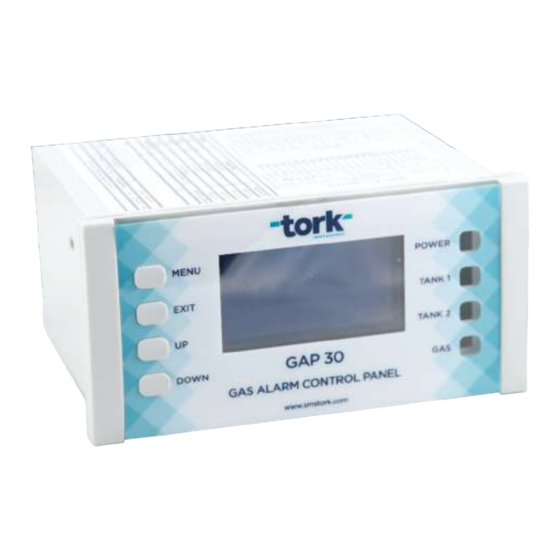
2. Identity 2.1. Description of the device GAP30 Gas Alarm Control Panel is a general-purpose, simple, easy and microprocessor-controlled device that can detect the output signal of detectors that can output in mA or voltage and can control the systems connected to the output relays according to the level of these signals, giving audible, light and visual warnings. -
Page 8: Front Of The Device
2.6. Back of the device The back side of the device is shown in the figure below to inform the user. Figure 2: Back of the device SMS-TORK Endüstriyel Otomasyon Ürünleri San. Tic. Ltd. Şti. -
Page 9: Terminal And Connection Points
2.7. Terminal and connection points DEFINITIONS (INPUTS) Device input : +24 VDC (Device Supply Voltage Pin) connection : GND (Device Supply Voltage Pin) Terminal 3 : GND (MAX485 Communication Pin) connection pins 4 : RXD(B) (MAX485 Communication Pin) definitions are : TXD(B) (MAX485 Communication Pin) given in the... -
Page 10: Technicial Features
Language option Turkish English User interface Graphic LCD display (blue-white), keys and warning leds Table 2: Technicial Features 2.9. Technical Dimensions Figure 5: Input Connection Terminals Şekil 5. Elektrikli Aktüatörün Vanaya Montajı SMS-TORK Endüstriyel Otomasyon Ürünleri San. Tic. Ltd. Şti. -
Page 11: Transport, Storage, Packaging, Warranty And Protection Measures
• The time spent in repair is added to the warranty period. The repair period of the product is maximum 20 business days. • The warranty starts from the date of notification of the product defect to the TORK authorized service, or in the absence of an authorized service station, to the seller, dealer, agency, representative, importer or manufacturer of the product. - Page 12 • In case the defective part is replaced with parts other than TORK Authorized technical services and/or parts without SMSTORK warranty • If it is determined by a report to be issued by the TORK authorized service, whether the malfunctions occur as a result of usage error or not.
-
Page 13: Protection Measures
• Use original packaging materials whenever possible. The responsibility of the damages that may occur during shipment due to improper packaging belongs to the customer. • Regarding the Warranty Certificate; For problems that may arise, an application can be made to the Ministry of Customs and Trade, General Directorate of Consumer Protection and Market Surveillance. -
Page 14: Splash Screen
De-energize and re-energize the device. If the problem persists, use a spare properly when booting device and contact the TORK manufacturer. Check the points where the input control signals are connected in the device and Continuous “GAS” alarm the environment where the detectors are located. -
Page 15: Monitoring Screens And Explanations
Gas sensors setting screen is given. There are status, signal selection, limit setting and alarm setting menus. Make the settings by following the steps given below. Figure 10: Gas Sensor Settings Screen SMS-TORK Endüstriyel Otomasyon Ürünleri San. Tic. Ltd. Şti. -
Page 16: Status: Making Status Settings
6. Press OK. Confirm the Save prompt and save the settings. A Saved message will appear stating that the settings have been saved. 7. If you want to exit without saving, press the EXIT button. SMS-TORK Endüstriyel Otomasyon Ürünleri San. Tic. Ltd. Şti. -
Page 17: Alarm: Making Alarm Settings
15. Press OK. Confirm the Save prompt and save the settings. A Saved message will appear stating that the settings have been saved. 16. If you want to exit without saving, press the EXIT button. SMS-TORK Endüstriyel Otomasyon Ürünleri San. Tic. Ltd. Şti. -
Page 18: Language Settings
NOTE Difficulty to be experienced as a result of incorrect TANK1, TANK2 and GAS settings. TankK1 and Tank2 settings are made as described in this section. Incorrect connections, wrong settings may prevent the device from working properly, as well as cause the connected systems to work incorrectly or not at all. -
Page 19: Electrical Connections
5. Electrical Connections 5.1. Connection of gas alarm detectors In the connection diagram below, GA21 gas alarm detectors, siren, power supply and output valve connection are given to the GAP30 gas alarm control panel as an example. Examine it. • Power supply is connected to pins 1 and 2. •... -
Page 20: Connection Of Tank Level Sensors
Relay outputs have a dry contact structure. It needs external voltage from outside. NOTE For example; If the system to be controlled will operate with 230VAC voltage, the user must pass 230V AC voltage through the relay contacts. 5.2. Connection of tank level sensors The connection diagram below shows two tank connections to the GAP30 gas alarm control panel as an example. -
Page 21: Tank 1 Connection
5.3. Tank 1 connection 5.2. It is explained under the title "5.2. Connection of tank level sensors". Examine it. GAP30 GAS ALARM PANEL TANK1 CONNECTION DIAGHRAM SUPPLY VOLTAGE LEVEL SENSOR GAP30 GAS ALARM PANEL VALVE 1 +24V DC voltage box +12V DC voltage box GND voltage box +T (4-20mA signal cable) - Page 22 www.smstork.com...
- Page 23 NOTE SMS-TORK Endüstriyel Otomasyon Ürünleri San. Tic. Ltd. Şti.
- Page 24 P +90 216 364 34 05 F +90 216 364 37 57 HEAD OFFICE P +90 262 290 20 20 F +90 262 290 20 21 FACTORY Çerkesli OSB Mah. Imes-2 Cad. No 5 Dilovası Kocaeli TURKEY SMS-TORK Endüstriyel Otomasyon Ürünleri San. Tic. Ltd. Şti.
Need help?
Do you have a question about the GAP 30 and is the answer not in the manual?
Questions and answers