Table of Contents
Advertisement
Quick Links
Advertisement
Table of Contents

Summary of Contents for EMTOP SBC930
- Page 1 SBC930 Evaluation Board User Manual Version 0.0 – Oct.21, 2019...
- Page 2 Embedded Solutions Specialist Revision History: Version Date Editor Description 2019-10-21 Jake Initial Version Website:www.emtop-tech.com Product Wiki: www.emtop-tech.com/wiki Sales: sales@emtop-tech.com Support: support@emtop-tech.com...
-
Page 3: Table Of Contents
10/100/1000M ethernet connector J21(not install default)..... 27 3.11 PCIe Connector CON8................. 30 3.12 Optional USB connector J19............... 32 3.13 HDMI connector J17................34 3.14 USB Double and 10/100/1000Mbps Ethernet Connector J2..35 3.15 Internal USB connector J18..............37 Website: www.emtop-tech.com Product Wiki: www.emtop-tech.com/wiki Sales: sales@emtop-tech.com Support: support@emtop-tech.com... - Page 4 ISPLAY EVICE CHAPTER 5 FUNCITON TEST....................68 LED T ......................... 68 RTC T ......................... 68 EEPROM T ........................69 MMC T ........................70 LVDS T ........................70 LVDS B ....................70 ACKLIGHT Website: www.emtop-tech.com Product Wiki: www.emtop-tech.com/wiki Sales: sales@emtop-tech.com Support: support@emtop-tech.com...
- Page 5 UILDING NVIRONMENT ......................... 75 UILD 6.2.1 Build U-Boot for MicroSD Boot............75 6.2.2 Build U-Boot for eMMC Boot............... 76 6.2.3 Update U-Boot Image................76 ........................76 UILD ERNEL TECHNICAL SUPPORT AND WARRANTY................78 Website: www.emtop-tech.com Product Wiki: www.emtop-tech.com/wiki Sales: sales@emtop-tech.com Support: support@emtop-tech.com...
-
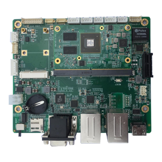
Page 6: Chapter 1 Product Overview
SDRAM and a 4~32GB eMMC, employ a 314 Pins gold finger mouth to spread out rich interfaces from the SOC. The base board named SBC930 which is design as an expansion board to carry the SOM-930-33. The flexible design allows the fast and easy way of realizing and upgrading the core baord’s capabilities. -
Page 7: Hardware Overview
User Name : SBC930 Password : Please contact with sales@emtop-tech.com 1.3 Hardware Overview The following sections list out all the hardware features of the two parts of SBC930 respectively. 1.2.1 SOM-930-33 Electric Features Working Temperature: 0 °C~ 70°C for commercial, -45 °C~70 °C for ... -
Page 8: Extension Board
Working Temperature: 0 °C~ 70°C Working Humidity: 20% ~ 90%, Non-Condensing Dimesions: 150m x 125m Input Voltage: 12V/2A Audio/Video Interfaces Single channel LVDS output support up to 1366*768@60Hz Website: www.emtop-tech.com Product Wiki: www.emtop-tech.com/wiki Sales: sales@emtop-tech.com Support: support@emtop-tech.com... - Page 9 UART3, 3-Line TTL Level, DIP Interface 8x GPIO Interfaces 1x mSATA interface 1x PCIe interface 1x Backlight output Input Interfaces and others A Reset Button Website: www.emtop-tech.com Product Wiki: www.emtop-tech.com/wiki Sales: sales@emtop-tech.com Support: support@emtop-tech.com...
-
Page 10: Chapter 2 Hardware System
2.2.2 USB to Ethernet LAN9500 The LAN950x is a high performances solution for USB to 10/100 Ethernet port bridging. With applications ranging from embedded systems, set-top boxes, and PVRs, to USB port Website: www.emtop-tech.com Product Wiki: www.emtop-tech.com/wiki Sales: sales@emtop-tech.com Support: support@emtop-tech.com... - Page 11 1080i. Analog RGB output and composite SYNC signal are also supported. The device accepts different data formats including RGB and YCbCr (e.g. RGB565, RGB666, RGB888, ITU656 like YCbCr, etc.). Both interlaced and noninterlaced input data formats Website: www.emtop-tech.com Product Wiki: www.emtop-tech.com/wiki Sales: sales@emtop-tech.com Support: support@emtop-tech.com...
-
Page 12: Hardware Interfaces
Embedded Solutions Specialist are supported. 16Mbit SDRAM is embedded in package. Frame rate conversion, Image rotation, zooming and scaling, are supported. 2.3 Hardware Interfaces 2.3.1 Dimension Drawing Website: www.emtop-tech.com Product Wiki: www.emtop-tech.com/wiki Sales: sales@emtop-tech.com Support: support@emtop-tech.com... - Page 13 Embedded Solutions Specialist 2.3.2 Function Block Website: www.emtop-tech.com Product Wiki: www.emtop-tech.com/wiki Sales: sales@emtop-tech.com Support: support@emtop-tech.com...
-
Page 14: Chapter 3 Detail Of Interface
Embedded Solutions Specialist Chapter 3 Detail of Interface 3.1 Connector of LVDS interface J7 1) Part Reference:J7 2) The circuit diagram is as follows, note that this circuit is only for reference. Website: www.emtop-tech.com Product Wiki: www.emtop-tech.com/wiki Sales: sales@emtop-tech.com Support: support@emtop-tech.com... - Page 15 3) 20Pin 2.00mm LVDS Connector mark Pin 1 with triangle, pin sequence is as follow Default Name Level BALL State Input/Output Note PWR_LVDS PWR_LVDS Default 3.3V output LVDS0_TX0_N Output LVDS0_TX0_P Output LVDS0_TX1_N Output LVDS0_TX1_P Output Website: www.emtop-tech.com Product Wiki: www.emtop-tech.com/wiki Sales: sales@emtop-tech.com Support: support@emtop-tech.com...
- Page 16 Default BIT_SEL Output pull down Optional output pull up to LVDS_PWR or pull down, Default BIT_SEL Output pull down 4) The specifications for 20Pin 2.00mm LVDS connector are as follows: Website: www.emtop-tech.com Product Wiki: www.emtop-tech.com/wiki Sales: sales@emtop-tech.com Support: support@emtop-tech.com...
-
Page 17: Backlight Connector J5
Embedded Solutions Specialist 3.2 Backlight connector J5 1) Part Reference:J5 2) The circuit diagram is as follows, note that this circuit is only for reference. Website: www.emtop-tech.com Product Wiki: www.emtop-tech.com/wiki Sales: sales@emtop-tech.com Support: support@emtop-tech.com... - Page 18 3) 5Pin Wafer Connector mark Pin 1 with triangle, pin sequence is as follow: Default Name Level BALL State Input/Output Note 12V OUT 12V Output BKL_EN 3.3V PU(100K) Input BKL_PWM 3.3V PU(100K) Input 4) 5Pin 1.25mm WaferThe specifications for are as follows: Website: www.emtop-tech.com Product Wiki: www.emtop-tech.com/wiki Sales: sales@emtop-tech.com Support: support@emtop-tech.com...
-
Page 19: Touch Interface J6
Embedded Solutions Specialist 3.3 Touch interface J6 1) Part Reference:J6 2) The circuit diagram is as follows, note that this circuit is only for reference. Website: www.emtop-tech.com Product Wiki: www.emtop-tech.com/wiki Sales: sales@emtop-tech.com Support: support@emtop-tech.com... - Page 20 3) 6Pin wafer connector mark Pin 1 with triangle, pin sequence is as follow: Default Name Level BALL State Input/Output Note 3.3V OUT 3.3V output I2C0_SCL 3.3V PU(100K) Input I2C0_SDA 3.3V PU(100K) Input CTP_INT 3.3V PU(100K) Input CTP_RST 3.3V PU(100K) Input Website: www.emtop-tech.com Product Wiki: www.emtop-tech.com/wiki Sales: sales@emtop-tech.com Support: support@emtop-tech.com...
-
Page 21: Usb For Touch Con2
Embedded Solutions Specialist 4) The specifications 6Pin 1.25mm Wafer for are as follows: 3.4 USB For Touch CON2 1) Part Reference:CON2 Website: www.emtop-tech.com Product Wiki: www.emtop-tech.com/wiki Sales: sales@emtop-tech.com Support: support@emtop-tech.com... - Page 22 2) 4Pin wafer connector mark Pin 1 with triangle, pin sequence is as follow: CON2 Default Name Level BALL State Input/Output Note 5V OUT Maxium 500mA USB7 difference - USB7 difference + 3) The specifications for 4Pin 2.5mm Wafer are as follows: Website: www.emtop-tech.com Product Wiki: www.emtop-tech.com/wiki Sales: sales@emtop-tech.com Support: support@emtop-tech.com...
-
Page 23: Rs232 Connector Con6
Embedded Solutions Specialist 3.5 RS232 connector CON6 1) Part Reference:CON6 2) The circuit diagram is as follows, note that this circuit is only for reference. Website: www.emtop-tech.com Product Wiki: www.emtop-tech.com/wiki Sales: sales@emtop-tech.com Support: support@emtop-tech.com... - Page 24 CON6 Default Name Level BALL State Input/Output Note 3.3V output,maxium 3.3V OUT 500mA RXD3 RS232 PU(100K) input TXD3 RS232 PU(100K) output 4) The specifications for 4Pin 2.5mm wafer are as follows: Website: www.emtop-tech.com Product Wiki: www.emtop-tech.com/wiki Sales: sales@emtop-tech.com Support: support@emtop-tech.com...
-
Page 25: Rs232 Connector Con4
Embedded Solutions Specialist 3.6 RS232 connector CON4 1) Part Reference:CON4 2) The circuit diagram is as follows, note that this circuit is only for reference. Website: www.emtop-tech.com Product Wiki: www.emtop-tech.com/wiki Sales: sales@emtop-tech.com Support: support@emtop-tech.com... - Page 26 4) Pin name description for CON4 CON4 Default Name Level BALL State Input/Output Note RXD0 RS232 PU(100K) Input TXD0 RS232 PU(100K) Output 5) 3Pin 2.5mm WaferThe specifications for are as follows: Website: www.emtop-tech.com Product Wiki: www.emtop-tech.com/wiki Sales: sales@emtop-tech.com Support: support@emtop-tech.com...
-
Page 27: Uart Connector Con5
Embedded Solutions Specialist 3.7 UART connector CON5 1) Part Reference:CON5 2) The circuit diagram is as follows, note that this circuit is only for reference. Website: www.emtop-tech.com Product Wiki: www.emtop-tech.com/wiki Sales: sales@emtop-tech.com Support: support@emtop-tech.com... - Page 28 3) 4Pin wafer connector mark Pin 1 with triangle, pin sequence is as follow: CON5 Default Name Level BALL State Input/Output Note 3.3V OUT Maxium 500mA UART2_RXD 3.3V PU(100K) Input UART2_TXD 3.3V PU(100K) Ouput 4) The specifications for 4Pin 2.5mm wafer are as follows: Website: www.emtop-tech.com Product Wiki: www.emtop-tech.com/wiki Sales: sales@emtop-tech.com Support: support@emtop-tech.com...
-
Page 29: Fan Connector Con11
Embedded Solutions Specialist 3.8 Fan connector CON11 1) Part Reference:CON11 2) The circuit diagram is as follows, note that this circuit is only for reference. Website: www.emtop-tech.com Product Wiki: www.emtop-tech.com/wiki Sales: sales@emtop-tech.com Support: support@emtop-tech.com... - Page 30 Power supply CPU Fan, 5V output default but can output 12V by changing ferrite, FAN_PWR_OUT maxium 500mA FAN_PWM 3.3V PU(100K) Input PWM output 4) The specifications for 3Pin 2.5mm wafer are as follows: Website: www.emtop-tech.com Product Wiki: www.emtop-tech.com/wiki Sales: sales@emtop-tech.com Support: support@emtop-tech.com...
-
Page 31: Reset Key S2
2) The circuit diagram is as follows, note that this circuit is only for reference. 3) The function for S2 is that reseting the core board by pushing the button down. Website: www.emtop-tech.com Product Wiki: www.emtop-tech.com/wiki Sales: sales@emtop-tech.com Support: support@emtop-tech.com... -
Page 32: 10/100/1000M Ethernet Connector J21(Not Install Default)
Embedded Solutions Specialist 4) The specifications for the key is as follow: 3.10 10/100/1000M ethernet connector J21(not install default) 1) Part Reference:J21 Website: www.emtop-tech.com Product Wiki: www.emtop-tech.com/wiki Sales: sales@emtop-tech.com Support: support@emtop-tech.com... - Page 33 2) The circuit diagram is as follows, note that this circuit is only for reference. Default not install these circuits and install PCIe connector CON8. 3) 10Pin wafer connector mark Pin 1 with triangle, pin sequence is as follow: Website: www.emtop-tech.com Product Wiki: www.emtop-tech.com/wiki Sales: sales@emtop-tech.com Support: support@emtop-tech.com...
- Page 34 2- Ethernet difference MDI2_P pair 2+ No Connector No Connector Ethernet difference MDI1_N pair 1- Ethernet difference MDI1_P pair 1+ Ethernet difference MDI0_N pair 0- Ethernet difference MDI0_P pair 0+ Website: www.emtop-tech.com Product Wiki: www.emtop-tech.com/wiki Sales: sales@emtop-tech.com Support: support@emtop-tech.com...
-
Page 35: Pcie Connector Con8
Embedded Solutions Specialist 4) The specifications for 10Pin 2.0mm wafer are as follows: 3.11 PCIe Connector CON8 1) Part Reference:CON8 Website: www.emtop-tech.com Product Wiki: www.emtop-tech.com/wiki Sales: sales@emtop-tech.com Support: support@emtop-tech.com... - Page 36 Embedded Solutions Specialist 2) The circuit diagram is as follows, note that this circuit is only for reference. 3) The specifications for PCIe connector are as follows: Website: www.emtop-tech.com Product Wiki: www.emtop-tech.com/wiki Sales: sales@emtop-tech.com Support: support@emtop-tech.com...
-
Page 37: Optional Usb Connector J19
Embedded Solutions Specialist 3.12 Optional USB connector J19 1) Part Reference:J19 2) 8Pin wafer connector mark Pin 1 with triangle, pin sequence is as follow: Website: www.emtop-tech.com Product Wiki: www.emtop-tech.com/wiki Sales: sales@emtop-tech.com Support: support@emtop-tech.com... - Page 38 500mA USB4 5V output, 5V OUT maxium 500mA USB3 difference - USB4 difference - USB3 difference + USB4 difference + 3) The specifications for 8Pin 2.0mm wafer are as follows: Website: www.emtop-tech.com Product Wiki: www.emtop-tech.com/wiki Sales: sales@emtop-tech.com Support: support@emtop-tech.com...
-
Page 39: Hdmi Connector J17
Embedded Solutions Specialist 3.13 HDMI connector J17 1) Part Reference:J17 2) The circuit diagram is as follows, note that this circuit is only for reference. Website: www.emtop-tech.com Product Wiki: www.emtop-tech.com/wiki Sales: sales@emtop-tech.com Support: support@emtop-tech.com... -
Page 40: Usb Double And 10/100/1000Mbps Ethernet Connector J2
Embedded Solutions Specialist 3) The specifications for HDMI connector are as follows: 3.14 USB Double and 10/100/1000Mbps Ethernet Connector 1) Part Reference:J2 Website: www.emtop-tech.com Product Wiki: www.emtop-tech.com/wiki Sales: sales@emtop-tech.com Support: support@emtop-tech.com... - Page 41 Embedded Solutions Specialist 2) The circuit diagram is as follows, note that this circuit is only for reference. 3) The specifications for USB double and 10/100/1000mbps ethernet connector are as follows: Website: www.emtop-tech.com Product Wiki: www.emtop-tech.com/wiki Sales: sales@emtop-tech.com Support: support@emtop-tech.com...
-
Page 42: Internal Usb Connector J18
1) Part Reference:J18 2) Note that this connector is connected with double usb with 10/100/1000mbps ethernet connector together. 3) 8Pin wafer connector mark Pin 1 with triangle, pin sequence is as follow: Website: www.emtop-tech.com Product Wiki: www.emtop-tech.com/wiki Sales: sales@emtop-tech.com Support: support@emtop-tech.com... - Page 43 500mA USB6 5V output,maxium 5V OUT 500mA USB5 difference - USB6 difference - USB5 difference + USB6 difference + Ground Ground 4) The specifications for 8Pin 2.0mm wafer are as follows: Website: www.emtop-tech.com Product Wiki: www.emtop-tech.com/wiki Sales: sales@emtop-tech.com Support: support@emtop-tech.com...
-
Page 44: Internal 10/100/1000Mbps Ethernet Connector J20
Embedded Solutions Specialist 3.16 Internal 10/100/1000Mbps Ethernet connector J20 1) Part Reference:J20 2) The circuit diagram is as follows, note that this circuit is only for reference. Website: www.emtop-tech.com Product Wiki: www.emtop-tech.com/wiki Sales: sales@emtop-tech.com Support: support@emtop-tech.com... - Page 45 3 + Ethernet difference GBE_MDI2_N pair 2 - Ethernet difference GBE_MDI2_P pair 2 + No connection No connection Ethernet difference GBE_MDI1_N pair 1 - Ethernet difference GBE_MDI1_P pair 1 + Website: www.emtop-tech.com Product Wiki: www.emtop-tech.com/wiki Sales: sales@emtop-tech.com Support: support@emtop-tech.com...
- Page 46 Ethernet difference GBE_MDI0_N pair 0 - Ethernet difference GBE_MDI0_P pair 0 + Note: All this diference pair function out by core board 5) The specifications for 10Pin 2.0mm wafer are as follows: Website: www.emtop-tech.com Product Wiki: www.emtop-tech.com/wiki Sales: sales@emtop-tech.com Support: support@emtop-tech.com...
-
Page 47: Usb Double And 10/100Mbps Connector J8
Embedded Solutions Specialist 3.17 USB Double and 10/100mbps connector J8 1) Part Reference:J8 2) The circuit diagram is as follows, note that this circuit is only for reference. Website: www.emtop-tech.com Product Wiki: www.emtop-tech.com/wiki Sales: sales@emtop-tech.com Support: support@emtop-tech.com... -
Page 48: Db9 And Vga Double Connector J11
Embedded Solutions Specialist 3) The specifications for USB double and 10/100Mbps connector are as follows: 3.18 DB9 and VGA double connector J11 1) Part Reference:J11 Website: www.emtop-tech.com Product Wiki: www.emtop-tech.com/wiki Sales: sales@emtop-tech.com Support: support@emtop-tech.com... - Page 49 2) The circuit diagram is as follows, note that this circuit is only for reference 3) Default installing DB9 only, optional installing DB9 and VGA double connector. 4) The specifications for DB9 and VGA double connector are as follows: Website: www.emtop-tech.com Product Wiki: www.emtop-tech.com/wiki Sales: sales@emtop-tech.com Support: support@emtop-tech.com...
-
Page 50: Tf Connector Con1
Embedded Solutions Specialist 3.19 TF Connector CON1 1) Part Reference:CON1 2) The circuit diagram is as follows, note that this circuit is only for reference: Website: www.emtop-tech.com Product Wiki: www.emtop-tech.com/wiki Sales: sales@emtop-tech.com Support: support@emtop-tech.com... -
Page 51: Boot Select Switch S1
Embedded Solutions Specialist 3) The specifications for TF Card connector are as follows: 3.20 Boot Select Switch S1 1) Part Reference:S1 Website: www.emtop-tech.com Product Wiki: www.emtop-tech.com/wiki Sales: sales@emtop-tech.com Support: support@emtop-tech.com... - Page 52 2) The circuit diagram is as follows, note that this circuit is only for reference: 3) Push up the S1 to select eMMC boot, and push down the S1 to select TF card boot. 4) The specifications for toggle swithc are as follows: Website: www.emtop-tech.com Product Wiki: www.emtop-tech.com/wiki Sales: sales@emtop-tech.com Support: support@emtop-tech.com...
-
Page 53: Power Connector J1
Embedded Solutions Specialist 3.21 Power Connector J1 1) Part Reference:J1 2) Pin sequence of 4Pin DIP connector is as follow Website: www.emtop-tech.com Product Wiki: www.emtop-tech.com/wiki Sales: sales@emtop-tech.com Support: support@emtop-tech.com... - Page 54 Embedded Solutions Specialist Default Name Level BALL State Input/Output Note 3) The specifications for 4Pin DIP connector are as follows: Website: www.emtop-tech.com Product Wiki: www.emtop-tech.com/wiki Sales: sales@emtop-tech.com Support: support@emtop-tech.com...
-
Page 55: Spi Connector Con10
3.22 SPI Connector CON10 1) Part Reference:CON10 2) 6Pin wafer connector mark Pin 1 with triangle, pin sequence is as follow: CON10 Default Name Level BALL State Input/Output Note SPI_CS 3.3V Output Website: www.emtop-tech.com Product Wiki: www.emtop-tech.com/wiki Sales: sales@emtop-tech.com Support: support@emtop-tech.com... - Page 56 Embedded Solutions Specialist SPI_CLK 3.3V Output CPU Input, slave SPI_DI 3.3V Output output CPU Output, slave SPI_DO 3.3V Output input 3.3V OUT 3) The specifications for 6Pin 2.5mm wafer are as follows: Website: www.emtop-tech.com Product Wiki: www.emtop-tech.com/wiki Sales: sales@emtop-tech.com Support: support@emtop-tech.com...
-
Page 57: Gpio Connector J12
Embedded Solutions Specialist 3.23 GPIO Connector J12 1) Part Reference:J12 2) 10Pin 2.00mm Connector mark Pin 1 with triangle, pin sequence is as follow Website: www.emtop-tech.com Product Wiki: www.emtop-tech.com/wiki Sales: sales@emtop-tech.com Support: support@emtop-tech.com... - Page 58 Input GPIO2_IO11 3.3V PU(100K) Input GPIO2_IO12 3.3V PU(100K) Input GPIO2_IO13 3.3V PU(100K) Input GPIO2_IO14 3.3V PU(100K) Input GPIO2_IO15 3.3V PU(100K) Input 3) The specifications for 10Pin 2.00mm connector are as follows: Website: www.emtop-tech.com Product Wiki: www.emtop-tech.com/wiki Sales: sales@emtop-tech.com Support: support@emtop-tech.com...
-
Page 59: Can Connector Con7
1) Part Reference:CON7 2) The circuit diagram is as follows, note that this circuit is only for reference. 3) 3Pin wafer connector mark Pin 1 with triangle, pin sequence is as follow: Website: www.emtop-tech.com Product Wiki: www.emtop-tech.com/wiki Sales: sales@emtop-tech.com Support: support@emtop-tech.com... - Page 60 Embedded Solutions Specialist CON7 Default Name Level BALL State Input/Output Note CANH CAN difference + CANL CAN difference - 4) The specifications for 3Pin 2.5mm wafer are as follows: Website: www.emtop-tech.com Product Wiki: www.emtop-tech.com/wiki Sales: sales@emtop-tech.com Support: support@emtop-tech.com...
-
Page 61: Cr2032 Battery Connector Jp10
CR2032 Battery Connector JP10 1) Part Reference:JP10 2) The circuit diagram is as follows, note that this circuit is only for reference. 3) The specifications for CR2032 battery connector are as follows: Website: www.emtop-tech.com Product Wiki: www.emtop-tech.com/wiki Sales: sales@emtop-tech.com Support: support@emtop-tech.com... -
Page 62: Msata Connector Cn1
Embedded Solutions Specialist 3.26 mSATA Connector CN1 1) Part Reference:CN1 2) The circuit diagram is as follows, note that this circuit is only for reference. Website: www.emtop-tech.com Product Wiki: www.emtop-tech.com/wiki Sales: sales@emtop-tech.com Support: support@emtop-tech.com... - Page 63 Embedded Solutions Specialist 3) The specifications for Mini PCIe connector are as follows: The specifications for matching nut are as follows: Website: www.emtop-tech.com Product Wiki: www.emtop-tech.com/wiki Sales: sales@emtop-tech.com Support: support@emtop-tech.com...
-
Page 64: Pci Connector Jp1
Embedded Solutions Specialist 3.27 PCI connector JP1 1) Part Reference:JP1 2) The specifications for PCI connector for core board are as follwos: Website: www.emtop-tech.com Product Wiki: www.emtop-tech.com/wiki Sales: sales@emtop-tech.com Support: support@emtop-tech.com... - Page 65 Embedded Solutions Specialist The informations for PCB of core board connector are as follows: Website: www.emtop-tech.com Product Wiki: www.emtop-tech.com/wiki Sales: sales@emtop-tech.com Support: support@emtop-tech.com...
-
Page 66: Chapter 4 Quick Start
Launch the tool program; Figure 4-1 Win32 Disk Imager Select system image, choose SBC930_SDCard.img, if it's SBC930_SDCard.im g.xz, please unzip it with 7-zip program and get SBC930_SDCard.img; Figure 4-2 Select target image Website: www.emtop-tech.com Product Wiki: www.emtop-tech.com/wiki Sales: sales@emtop-tech.com Support: support@emtop-tech.com... - Page 67 Embedded Solutions Specialist Website: www.emtop-tech.com Product Wiki: www.emtop-tech.com/wiki Sales: sales@emtop-tech.com Support: support@emtop-tech.com...
-
Page 68: Boot From Microsd Card
Board: SM9300 I2C: ready DRAM: 1 GiB MMC: FSL_SDHC: 0, FSL_SDHC: 1 *** Warning - bad CRC, using default environment Display: SVGA-lvds (800x600) serial Out: serial Err: serial Can't find PMIC:PFUZE100 Website: www.emtop-tech.com Product Wiki: www.emtop-tech.com/wiki Sales: sales@emtop-tech.com Support: support@emtop-tech.com... - Page 69 IPv6: ADDRCONF(NETDEV_UP): usb0: link is not ready FAT-fs (mmcblk1p1): Volume was not properly unmounted. Some data may be corrupt. Please run fsck. Debian GNU/Linux 8 arm ttymxc0 www.embest-tech.com default username:password is [root:root] arm login: Website: www.emtop-tech.com Product Wiki: www.emtop-tech.com/wiki Sales: sales@emtop-tech.com Support: support@emtop-tech.com...
-
Page 70: Fuse Emmc Image
Command (m for help): Partition number (1,2, default 2): Partition 2 has been deleted. Command (m for help): Partition type primary (1 primary, 0 extended, 3 free) extended (container for logical partitions) Website: www.emtop-tech.com Product Wiki: www.emtop-tech.com/wiki Sales: sales@emtop-tech.com Support: support@emtop-tech.com... -
Page 71: Boot From Emmc
The LOGO file is under partition1 (FAT) of MicroSD/eMMC device named LOGO.bmp. Replace it with a 24bpp RGB BMP format picture. 4.5.2 Replace Linux LOGO Right now, the BSP doesn't display Linux logo, but only displays booting message. Website: www.emtop-tech.com Product Wiki: www.emtop-tech.com/wiki Sales: sales@emtop-tech.com Support: support@emtop-tech.com... -
Page 72: Set Display Device
The board chooses LVDS/VGA as the default display device. If you want to change it to HDMI displayer, please enter into u-boot prompt: U-Boot > setenv panel HDMI; saveenv; reset Or restore LVDS/VGA: U-Boot > setenv panel SVGA-lvds; saveenv; reset Website: www.emtop-tech.com Product Wiki: www.emtop-tech.com/wiki Sales: sales@emtop-tech.com Support: support@emtop-tech.com... -
Page 73: Chapter 5 Funciton Test
Thu Jan 1 00:02:22 UTC 1970 Set system time root@arm:~# date -s "2019-10-12 10:30:00" Sat Oct 12 10:30:00 UTC 2019 Wirite system time into hardware RTC Website: www.emtop-tech.com Product Wiki: www.emtop-tech.com/wiki Sales: sales@emtop-tech.com Support: support@emtop-tech.com... -
Page 74: Eeprom Test
-Cv -n 256 /sys/bus/i2c/devices/2-0050/eeprom 00000000 48 65 6c 6c 6f 20 53 42 43 39 33 30 20 69 4d 58 |Hello SBC930 iMX| 00000010 36 51 0a ff ff ff ff ff ff ff ff ff ff ff ff ff |6Q....| 00000020 ff ff ff ff ff ff ff ff ff ff ff ff ff ff ff ff |....|... -
Page 75: Emmc Test
5 > /sys/class/backlight/backlight_lvds/brightness 5.7 Capacitive Touchscreen Test 5.8 VGA Test Please refer chapter Set Display Device to choose LVDS/VGA output. When board boots up, the VGA display panel will show booting message. Website: www.emtop-tech.com Product Wiki: www.emtop-tech.com/wiki Sales: sales@emtop-tech.com Support: support@emtop-tech.com... -
Page 76: Hdmi Test
5.11 Network Test Connect RJ45 with network router via ethernet cable, request IP from the router and ping remote host. root@arm:~# dhclient -v eth0 Listening on LPF/eth0/fa:c1:dd:46:c0:cc Sending on LPF/eth0/fa:c1:dd:46:c0:cc Website: www.emtop-tech.com Product Wiki: www.emtop-tech.com/wiki Sales: sales@emtop-tech.com Support: support@emtop-tech.com... -
Page 77: Pcie Test
3.297561] pci 0000:00:00.0: PCI bridge to [bus 01] 3.322317] pcieport 0000:00:00.0: Signaling PME through PCIe PME interrupt 3.329153] pci 0000:01:00.0: Signaling PME through PCIe PME interrupt 3.496440] e1000e 0000:01:00.0 eth2: (PCI Express:2.5GT/s:Width x1) Website: www.emtop-tech.com Product Wiki: www.emtop-tech.com/wiki Sales: sales@emtop-tech.com Support: support@emtop-tech.com... -
Page 78: Canbus Test
2-1.6:1.0: USB Mass Storage device detected scsi host2: usb-storage 2-1.6:1.0 scsi 2:0:0:0: Direct-Access Generic- Multi-Card 1.00 PQ: 0 ANSI: 4 sd 2:0:0:0: [sdb] 31116288 512-byte logical blocks: (15.9 GB/14.8 GiB) Website: www.emtop-tech.com Product Wiki: www.emtop-tech.com/wiki Sales: sales@emtop-tech.com Support: support@emtop-tech.com... -
Page 79: Sata Test
1 root root 0 Jan 1 00:15 0:0:0:0 -> ../../devices/soc0/soc/2200000.sata/a ta1/host0/target0:0:0/0:0:0:0/scsi_device/0:0:0:0 lrwxrwxrwx 1 root root 0 Jan 1 00:23 2:0:0:0 -> ../../devices/soc0/soc/2100000.aips-b us/2184200.usb/ci_hdrc.1/usb2/2-1/2-1.6/2-1.6:1.0/host2/target2:0:0/2:0:0:0/scsi_device/2: 0:0:0 root@arm:~# ls /sys/class/scsi_device/0:0:0:0/device/block So the SATA device is /dev/sda. Website: www.emtop-tech.com Product Wiki: www.emtop-tech.com/wiki Sales: sales@emtop-tech.com Support: support@emtop-tech.com... -
Page 80: Chapter 6 System Building
Please get u-boot source code u-boot*.tar.xz from SDK package. $ tar -xvf <YOUR_PATH>/u-boot*.tar.xz -C $HOME/work $ cd $HOME/work/u-boot 6.2.1 Build U-Boot for MicroSD Boot $ make distclean $ make embest_fsl_sm9300_sdcard_defconfig $ make -j6 Website: www.emtop-tech.com Product Wiki: www.emtop-tech.com/wiki Sales: sales@emtop-tech.com Support: support@emtop-tech.com... -
Page 81: Build U-Boot For Emmc Boot
Get kernel source code linux.tar.xz for SDK package. $ tar -xvf <YOUR_PATH>/linux.tar.xz -C $HOME/work $ cd $HOME/work/linux $ make distclean $ make embest_fsl_sm9300_defconfig $ make dtbs zImage -j6 Website: www.emtop-tech.com Product Wiki: www.emtop-tech.com/wiki Sales: sales@emtop-tech.com Support: support@emtop-tech.com... - Page 82 After compilation is completed, it will generate below files: arch/arm/boot/dts/imx6q_sbc930.dtb arch/arm/boot/dts/imx6q_sbc930_hdmi.dtb arch/arm/boot/zImage Copy these files to MicroSD or eMMC partion1(VFAT), and edit uEnv.txt to choose fdt_file: imx6q_sbc930.dtb Without HDMI imx6q_sbc930_hdmi.dtb With HDMI Website: www.emtop-tech.com Product Wiki: www.emtop-tech.com/wiki Sales: sales@emtop-tech.com Support: support@emtop-tech.com...
-
Page 83: Technical Support And Warranty
Embedded Solutions Specialist Technical Support and Warranty Technical Support EMTOP TECHNOLOGY provides its product with one-year free technical support including: Providing software and hardware resources related to the embedded products of EMTOP TECHNOLOGY; Helping customers properly compile and run the source code provided by ... - Page 84 G. Products purchased from unauthorized sales; H. Warranty (including verbal and written) that is not made by EMTOP TECHNOLOGY and not included in the scope of our warranty should be fulfilled by the party who committed. EMTOP TECHNOLOGY has no any responsibility;...
- Page 85 Please contact technical support if there is any repair request. Note: EMTOP TECHNOLOGY will not take any responsibility on the products sent back without the permission of the company. Contact Information Pre-sales: sales@emtop-tech.com...
Need help?
Do you have a question about the SBC930 and is the answer not in the manual?
Questions and answers