Table of Contents
Advertisement
Quick Links
Advertisement
Table of Contents

Related Manuals for PureAire Monitoring Systems Air Check EX ST-46


Summary of Contents for PureAire Monitoring Systems Air Check EX ST-46
- Page 1 Air Check ST-46 LEL Gas Monitor Instruction Manual PureAire Monitoring Systems, Inc. 1140 Ensell Road Lake Zurich, Illinois 60047 Phone: 847-726-6000 Fax: 847-726-6051 Toll-Free: 888-788-8050 www.Pureairemonitoring.com Rev 1.1 August 2023...
- Page 2 That’s just one way PureAire takes that extra step to ensure your complete satisfaction. Thank you again for investing in PureAire Monitoring Systems for your monitoring needs and I’m proud to welcome you to our family of valued and satisfied customers.
-
Page 3: Table Of Contents
PureAire Monitoring Systems, Inc. 10/25/07 Table of Contents 1: Introduction......................4 1.1 Component Identification ................5 1.1.1 Front Panel ..................6 1.1.2 Overall ..................... 6 1.1.3 Gas Sensor ..................6 2: Specifications ..................... 7 2.1 Performance Specifications ............... 7 2.2 Gas Detection Systems ................7 2.3 Signal Outputs ................... - Page 4 PureAire Monitoring Systems, Inc. 10/25/07 7: Appendix ......................20 7.1 Modbus RS-485 Serial Interface.............. 20 7.1.1 RTU Address ................. 20 7.1.2 Modbus Data Registers and Function Codes ......... 20 7.1.3 Modbus Configuration Software ........... 22 7.2 Alarm Relays ..................23 7.2.1 Alarm 3 (Sensor Fault Alarm) ..............
-
Page 5: 1: Introduction
PureAire Monitoring Systems, Inc. 10/25/07 1: Introduction The Air Check EX is an explosion-proof toxic gas monitoring system designed for the continuous detection and measurement of toxic gas leaks. It is a single point monitoring system housed in an explosion-proof enclosure. The enclosure is suitable for use in Class 1, Group B, C, D and Class 2, Group E, F, and G hazardous areas. -
Page 6: Component Identification
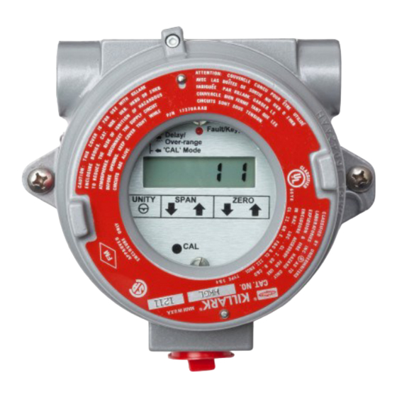
PureAire Monitoring Systems, Inc. 10/25/07 1.1 Component Identification 1.1.1 Front Panel Fault / Keypad Digital Display Left Indicator Arrow Reset Key (magnetic) Span and Zero Adjustment Keys Calibration Key (magnetic) (magnetic) Digital Display — A 3½ digit LCD which continuously displays the measured gas concentration value when in the normal monitoring mode. -
Page 7: Front Panel
PureAire Monitoring Systems, Inc. 10/25/07 1.1.2 Overall Explosion-Proof Housing — Meets requirements for installation in Class 1, Group B, C, and D and Class 2, Group E, F, and G hazardous areas. Magnetic keypad permits calibration without declassifying area. Front Panel — Incorporates local digital display, magnetic keys, etc. See 1.1.1 above for front panel component details. -
Page 8: 2: Specifications
PureAire Monitoring Systems, Inc. 10/25/07 2: Specifications 2.1 Performance Specifications Sensor Type: Disposable, LEL catalytic bead Response Time: Within 30 seconds to T90. Repeatability: ±10% of full scale. Operating Temperature: 14° to 113°F (0° to +40°C); consult PureAire for lower operating temperatures. -
Page 9: Safety Characteristics
PureAire Monitoring Systems, Inc. 10/25/07 2.6 Safety Characteristics Transmitter enclosure suitable for Class 1, Group B, C, D and Class 2, Group E, F, and G hazardous areas. Also meets NEMA 4 with included O-ring. -
Page 10: 3: Installation
PureAire Monitoring Systems, Inc. 10/25/07 3: Installation 3.1 Mounting The Air Check EX monitoring system is packaged in an explosion-proof housing with three ¾ inch NPT conduit hubs. The system should be mounted on a vibration-free surface and out of direct sunlight. -
Page 11: Optional Outputs
PureAire Monitoring Systems, Inc. 10/25/07 3.3 Optional Outputs NOTE: The Air Check EX may be configured with one of the following optional outputs isolated 4-20 mA, Modbus serial output, SPDT alarm relays. Optional outputs are provided using an auxiliary, factory-installed electronics board. -
Page 12: Modbus Rs-485 Serial
PureAire Monitoring Systems, Inc. 10/25/07 3.3.2 Modbus RS-485 Serial Interface The Modbus RS-485 Serial Interface board allows up to 128 Air Check EX gas monitors to communicate to a Modbus master device on a single cable. The gas detector functions as a slave device; a PLC or PC running MMI or BUI software equipped with a Modbus driver functions as the master. -
Page 13: Alarm Relays
PureAire Monitoring Systems, Inc. 10/25/07 3.3.3 Alarm Relays The alarm option provides 5-amp resistive form C relays for Alarm 1, Alarm 2, and Alarm 3 conditions. They may be wired for either normally open or normally closed operation. IMPORTANT: The relay contacts are rated for 5 amp resistive loads. -
Page 14: 4: Normal Operation
PureAire Monitoring Systems, Inc. 10/25/07 4: Normal Operation The Air Check EX is a single point monitoring system designed for the continuous detection and measurement of toxic gas leaks. 4.1 Power Up Delay The Air Check EX incorporates a power up delay that holds the analog output at 4 mA for one minute after power is applied. -
Page 15: Alarm Reset
PureAire Monitoring Systems, Inc. 10/25/07 4.6 Alarm Reset If the instrument is equipped with the Alarm Relays option and one or more alarms are configured for latching operation (see Appendix), alarm conditions must be acknowledged by manually resetting the alarm. This manual alarm reset may be performed remotely via a control room signal or locally by holding the magnet at about the 7 o’clock position on the base of the cover assembly. -
Page 16: Routine Maintenance Schedule
PureAire Monitoring Systems, Inc. 10/25/07 4.8 Routine Maintenance Schedule Continuous gas detection systems depended upon to measure and detect hazardous gas leaks in the workplace require periodic maintenance to ensure proper operation. The frequency with which this routine maintenance is required depends on the environment, since temperature, humidity, gas concentrations, and dust all affect system operation. -
Page 17: 5: Maintenance & Calibration
PureAire Monitoring Systems, Inc. 10/25/07 5: Maintenance & Calibration Maintenance and calibration should be performed only by qualified personnel. 5.1 Sensor Calibration The Air Check EX system requires periodic calibration with the appropriate standard gas. Calibration should be performed whenever 6 to 12 months has passed. -
Page 18: Span Calibration Direct From Cylinder Gas
PureAire Monitoring Systems, Inc. 10/25/07 5.1.4 Span Calibration from span gas cylinders CAUTION: Be sure to observe all safety guidelines when generating and using calibration gases. Connect p/n 690100 calibration cap to the LEL sensor cell. IMPORTANT: Be sure to perform the calibration with certified span gas and within the recommended use date. -
Page 19: Displaying Zero/Gain Settings
PureAire Monitoring Systems, Inc. 10/25/07 5.1.5 Displaying Zero / Gain Settings The Zero and Span values applied during calibration may be read on the front panel of the LCD after exiting the Calibration mode. These values provide an indication of how much sensor sensitivity has declined over time — the higher the gain, the greater the degree of sensor sensitivity deterioration. -
Page 20: 6: Diagrams & Schematics
PureAire Monitoring Systems, Inc. 10/25/07 6: Diagrams & Schematics 6.1 Dimensional Drawing LEL catalytic sensor cell... -
Page 21: 7: Appendix
PureAire Monitoring Systems, Inc. 10/25/07 7: Appendix 7.1 Modbus RS-485 Serial Interface The optional Modbus RS-485 serial interface board allows up to 128 Air Check EX gas monitors to communicate to a Modbus master device — such as a PLC or PC running MMI or GUI software equipped with a Modbus driver —... - Page 22 PureAire Monitoring Systems, Inc. 10/25/07 Variable Alias Read Function Code Write Function Code A2D ASCII 31010 (6 bytes) 3 & 4 6 bytes of data representing the scaled span value, including the decimal point. The first 5 bytes contain the value; the last byte is a space. They are arranged with the first byte as the MSD with leading zero spacing.
-
Page 23: Modbus Configuration Software
PureAire Monitoring Systems, Inc. 10/25/07 7.1.3 Modbus Configuration Software All of the register values described in 7.1.2 above must be configured via the serial port. This is a one time requirement unless changes within the application necessitate adjustments after the initial installation. This functionality may be built into the Modbus master or may be performed with a portable computer running a simple software application. -
Page 24: Alarm Relays
PureAire Monitoring Systems, Inc. 10/25/07 7.2 Alarm Relays The Alarm option provides 5-amp resistive form C relays for Alarm 1, Alarm 2, and Alarm 3 conditions. IMPORTANT: The relay contacts are rated for 5 amp resistive loads. Appropriate surge suppressors should be installed across loads to prevent arcing on the contacts. -
Page 25: Alarm Relay Configuration
PureAire Monitoring Systems, Inc. 10/25/07 7.2.3 Alarm Relay Configuration (Polarity) Alarms 1, 2, and 3 may be configured in for latching / non-latching operation, fail-safe operation, etc. The exact configuration of these alarms is determined by the positions chosen on the FUNCTION DIP switch. -
Page 26: Connecting Remote Digital Display
PureAire Monitoring Systems, Inc. 10/25/07 7.3 Remote Digital Display Remote Display Alarm Indicator for LEL monitor (Part number 99091) The Remote Display Alarm Indicator is designed to display remote LEL percent concentration information from PureAire’ Combustible monitors. All PureAire Combustible LEL monitors have a built in 4-20mA output. The remote display alarm easily connects to the monitor’s input power and mA... - Page 27 PureAire Monitoring Systems, Inc. 10/25/07 Mount the case to a wall or other flat surface. There are 4ea. through holes for fastening the case. The case is designed to be flush mounted. NOTE: The front cover can be removed from the case by gently pulling on the plastic hinges.
- Page 28 PureAire Monitoring Systems, Inc. 10/25/07 Identification of switches and controls 1. Alarm Adjusting Switches – These switches are used select the alarm level to be adjusted. They are factory set at 20% LEL for Alarm 1 and 40% LEL for Alarm 2.
- Page 29 PureAire Monitoring Systems, Inc. 10/25/07 How to set the zero and full scale range This will need to be set up in the field to adjust to the length of cable between the combustible LEL monitor and the remote display alarm indicator. (See Section 3.3 Optional outputs 4-20mA loop).
- Page 30 PureAire Monitoring Systems, Inc. 10/25/07 CAUTION: If the LEL monitor is in the measuring mode and the ZERO push button is pressed on the remote digital display, an “Err” will be displayed on the remote display and no readings will be recorded. If the SPAN push button is pressed in the measuring mode, the remote display will automatically adjust to full LEL scale.
Need help?
Do you have a question about the Air Check EX ST-46 and is the answer not in the manual?
Questions and answers