Table of Contents
Advertisement
Quick Links
Advertisement
Table of Contents

Summary of Contents for OTEK M667TP
- Page 1 Version 1.0 Sep. 2011 User Manual Model No. M667TP Point-of-Sale Hardware System...
- Page 2 Copyright 2011 All Rights Reserved Manual Version 1.0 Part Number: The information contained in this document is subject to change without notice. We make no warranty of any kind with regard to this material, including, but not limited to, the implied warranties of merchantability and fitness for a particular purpose.
- Page 3 Safety IMPORTANT SAFETY INSTRUCTIONS To disconnect the machine from the electrical Power Supply, turn off the power switch and remove the power cord plug from the wall socket. The wall socket must be easily accessible and in close proximity to the machine. Read these instructions carefully.
- Page 4 CAUTION ON LITHIUM BATTERIES There is a danger of explosion if the battery is replaced incorrectly. Replace only with the same or equivalent type recommended by the manufacturer. Discard used batteries according to the manufacturer’s instructions. Battery Caution Risk of explosion if battery is replaced by an incorrectly type. Dispose of used battery according to the local disposal instructions.
- Page 5 The crossed dustbin symbol on the device means that it should not be disposed of with other household wastes at the end of its working life. Instead, the device should be taken to the waste collection centers for activation of the treatment, collection, recycling and disposal procedure.
- Page 6 Revision History Changes to the original user manual are listed below: Revision Date Description V1.0 Sep, 2011 Release ( C46 M/B )
-
Page 7: Table Of Contents
Table Contents 1 Item Checklist............ 1 Standard Items ..............1 Optional Items ..............2 2 System View............3 Front View ................3 Rear View................4 Bottom View ................. 5 I/O View................6 3 Peripheral Installation........7 MSR ..................7 Second Display ..............8 Cash Drawer .............. - Page 8 7 BIOS Settings...........26 Appendix ..............30...
-
Page 9: Item Checklist
Item Checklist Take the system unit out of the carton. Remove the unit from the carton by holding it by the foam inserts. The following contents should be found in the carton: Standard Items a. System b. Driver CD c. Power Adapter (65W) d. -
Page 10: Optional Items
Optional Items a. MSR Module b. Second Display... -
Page 11: System View
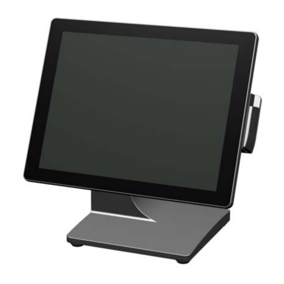
System View Front View ① ② Number Description Touch Screen MSR Module (Option) -
Page 12: Rear View
Rear View ③ ④ ⑤ ⑥ Number Description Cable Cover Stand/Wall Mount Kit Installing Place Stand Use the power switch to turn the system power ON or OFF. -
Page 13: Bottom View
Bottom View ⑦ Number Description Stand Pad... -
Page 14: I/O View
I/O View ④ ⑥ ① ② ⑨ ③ ⑤ ⑦ ⑧ Number Description E-SATA connector (for OP15) Power Jack for HDD (for OP15) Cash Drawer USB x 4 COM1~4 (from left to right) Power Jack for System Power Button Note: The maximum current that can be drawn from each COM port is 500 mA. -
Page 15: Peripheral Installation
Peripheral Installation The peripheral and modules units provided are tested and can be supplied at your request. Components of MSR Kit: Screws Slide the MSR into the right position of the System. Fasten the screws (x2). -
Page 16: Second Display
Second Display (USB Interface) Components of Second Display Kit: Metal Bracket Second Display USB Cable Screws ❷ ❸ ❶ ❶ ❷ ❸ Fix the parts of Second Display modules as steps as above picture shows. (detail steps as below) ❶ Put the second display upside down. - Page 17 Fasten the scrws (x3) to fix the Second Display moudle with the System. Connect the USB cable to the System. Finish.
- Page 18 Second Display(VGA Interface with POWER +12V) Components of Second Display Kit: Metal Bracket Second Display Screws USB Cable ❷ ❸ ❶ ❶ ❷ ❸ Fix the parts of Second Display modules as steps 1. as above picture shows. (detail steps as below) ❶...
- Page 19 Fasten the scrws (x3) to fix the Second Display moudle with the System. Connect the VGA cable to the System. Finish.
-
Page 20: Cash Drawer
Cash Drawer You can install a cash drawer through the cash drawer port. Please verify the pin assignment before installation. Cash Drawer Pin Assignment Signal DOUT bit0 DIN bit0 12V / 19V DOUT bit1 Cash Drawer Controller Register The Cash Drawer Controller use one I/O addresses to control the Cash Drawer. Register Location: 48Ch Attribute: Read / Write Size: 8bit... - Page 21 Bit 7: Reserved Bit 6: Cash Drawer “DIN bit0” pin input status. = 1: the Cash Drawer closed or no Cash Drawer = 0: the Cash Drawer opened Bit 5: Reserved Bit 4: Reserved Bit 3: Cash Drawer “DOUT bit1” pin output control. = 1: Opening the Cash Drawer = 0: Allow close the Cash Drawer Bit 2: Cash Drawer “DOUT bit0”...
-
Page 22: System Assembly & Disassembly
System Assembly & Disassembly Replace the HDD Unfasten the screw (x1). Slide out the HDD Cover. Unfasten the screws (x4) Separate the HDD from the metal bracket. -
Page 23: Remove The System Stand
Remove the System Stand Open the hinge cap and cable cover. Release the screws (x4) for the VESA mounting plate and the LCD rear cover. Remove the stand. -
Page 24: Remove The Lcd Rear Cover
Remove the LCD Rear Cover Remove the system stand (Chapter 4-2). Unfasten the screws (x4) to separate the LCD Rear Cover. Gently flip up the Rear cover. Note: Please release all the connectors on the Motherboard before you completely open the Rear cover. -
Page 25: Replace The Motherboard
Replace the Motherboard To open the LCD rear cover first as steps in Chapter 4-3. Unfasten the screws (x5) on the Motherboard. Unfasten the hex screws (x2) to release the I/O metal panel from the Motherboard. Replace the Inverter Board To open the LCD rear cover first (see Chapter 4-3). -
Page 26: Replace The Lcd Panel
Replace the LCD Panel Touch LCD Bezel Remove the LCD rear Cover (Chapter 4-3) Release all the connectors on the Motherboard (Chapter 4-3) Release inverter cables & touch cables (Chapter 4-5 and 4-6) Remove the screws (x4) to separate the Touch LCD bezel from the LCD Panel Module. -
Page 27: Specification
Specification Model Name M667TP Motherboard CPU Support Intel Pine View D525 Duo Core 1.8G, L2 1M, FSB667 / 800MHz Chipset CPU integrated graphic + ICH8M System Memory 1 x DDR3 SO-DIMM socket up to 2GB Graphic Memory Intel GMA 3150 share system memory up to 256MB... - Page 28 Environment EMC & Safety FCC/CE Class A, LVD Operating Temperature 5℃ ~ 35℃ (41℉ ~ 104℉) -20℃ ~ 55℃ (-4℉ ~ 131℉) Storage Temperature Operating Humidity 20% ~ 80% RH non condensing Storage Humidity 20% ~ 85% RH non condensing Dimension (W x D x H) 361.6 x 220 x 339.3 mm Weight (N.W./G.W.)
-
Page 29: Jumper Settings
Jumper Settings C46 Motherboard 6-1-1 Motherboard Layout... - Page 30 6-1-2 Connectors & Functions Connector Function Speaker & MIC CONN SATA Power LAN LED CONN For external Touch Card reader CN10/14 T-COM CONN CN11 RF CONN CN12 PS2 Keyboard CN13 HDD LED CONN CN15 FT STATUS INTERFACE CN16 Inverter CN17 TUOCH CN18 Power LED CONN...
- Page 31 6-1-3 Jumper Settings CD Power Setting Function (1-2) (3-4) ▲12V Power Mode Setting Function (1-2) ▲ATX Power AT Power CMOS Operation Mode Function (1-2) ▲CMOS Normal CMOS Reset System Reset Function (1-2) ▲System Normal System Reset...
- Page 32 CRT Power Ctrl Function (1-2) ▲HW BIOS COM Power Setting Function (1-2) (3-4) (5-6) (7-8) ▲COM3 5V COM3 12V COM4 5V ▲COM4 12V Inverter Selection Function JP10 (1-2) (3-4) (5-6) ▲CCFL...
- Page 33 LCD ID Setting LVDS Resolution Output Interface Bits Channel (1-2) (3-4) (5-6) (7-8) Single 1024 Single 1366 Single : LCD Panel : VGA Port Single *800 Single 1024 Single 1280 X 1024 Dual : LCD Panel *Note: specialized for Sharp 12.1” LQ121S1LG41/LQ121S1LG42 panel.
- Page 34 BIOS Settings BIOS Main Menu When the BIOS Main Menu is displayed, the following items can be selected. Use the arrow keys to select items and the Enter key to accept and enter the sub-menu. Note: The BIOS setup menus shown in this section are for reference only and may not exactly match the items of your BIOS version.
- Page 35 PnP/PCI Configurations This entry appears if your system supports Plug and Play and PCI Configuration. PC health status Displays CPU, System Temperature, Fan Speed, and System Voltages Value. Load Optimized Defaults Use this menu to load the BIOS default values, i.e., factory settings for optimal performance system operations.
- Page 36 VGA with 12V Setting 1、 Turn on power than click “Del” for BIOS SETUP 2、 Select Power Configuration COM/VGA Ports 3、 Select VGA Power Setting...
- Page 37 4、Change No Power to +12V 5、Press F10 to save...
- Page 38 Appendix Drivers Installation: The shipping package includes a Driver CD. You can find every individual driver and utility that enables you to install the drivers in the Driver CD. Please insert the Driver CD into the drive and double click on the “index.htm” to pick up the models.
Need help?
Do you have a question about the M667TP and is the answer not in the manual?
Questions and answers