Table of Contents
Advertisement
Quick Links
Advertisement
Table of Contents

Summary of Contents for RIVIAN PT00057325
- Page 1 JUNE 2022 W A L L C H A R G E R Installation Guide PRODUCT NUMBER PT00057325...
- Page 2 © 2021-2022 Rivian Automotive, LLC. All rights reserved. All information in this document and all Rivian software is subject to copyright and other intellectual property rights of Rivian Automotive, LLC, its affiliates, or its licensors. This material may not be modified, reproduced, or copied, in whole or in part, without the prior written permission of Rivian Automotive, LLC, its affiliates, or its licensors.
-
Page 3: Table Of Contents
Contents Important Safety Instructions SAVE THESE INSTRUCTIONS Precautions Safety Symbols on Hardware Labels Introduction Identify Parts Tools Remove the Faceplate Installation Select an Installation Location Attach the Mounting Plate Attach the Wall Charger to the Mounting Plate Set the Operating Current Connect Conductors Install the Faceplate Wrap and Dock the Cable... - Page 4 Customer Service...
-
Page 5: Important Safety Instructions
Important Safety Instructions SAVE THESE INSTRUCTIONS DANGER Read all the instructions before installing the Rivian Wall Charger. Follow the safety instructions and warnings in this guide when installing the Wall Charger. Failure to do so may result in fire, electrical shock, serious injury, or death. - Page 6 No user serviceable parts inside. Refer servicing to qualified service personnel. Do not put fingers into the coupler. Do not use this equipment if the flexible power cord or cable is frayed, has broken insulation, or any other signs of damage. ...
- Page 7 Risk of Personal Injury DANGER Disconnect the power supply before installing or repairing the Wall Charger. Failure to do so may result in physical injury or damage to the power supply system and the Wall Charger. Keep any packing materials away from children. These materials are a potential source of danger, and can cause suffocation.
- Page 8 ESD (electrostatic discharge) protection. Rivian does not recommend using a GFCI breaker since the Wall Charger has charging circuit interrupting device (CCID20) protection. Using a GFCI breaker in the panel can cause nuisance tripping. If local codes require a GFCI breaker for plug-in installation, Rivian recommends a hardwire installation.
-
Page 9: Safety Symbols On Hardware Labels
SAFETY SYMBOLS ON HARDWARE LABELS The following safety symbols may appear on labels located on hardware used in this installation. Risk of Electric Shock Danger Phase Equipment Ground Instruction Manual UL Logo... -
Page 10: Introduction
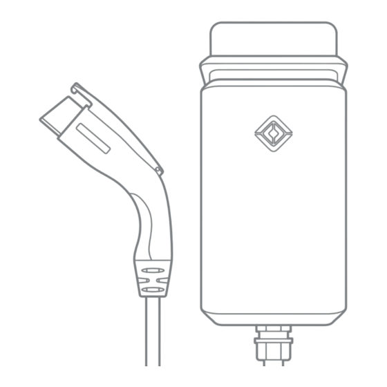
Introduction This document provides installation instructions for the Rivian Wall Charger. It also includes instructions on how to connect the Wall Charger to WiFi and to a Rivian account. Identify Parts 1. Wall Charger 4. Two 13 mm M4 Phillips screws (to attach the charger to the mounting ... -
Page 11: Tools
Tools Required Optional #2 Phillips screwdriver Hole saw Security T20 Torx screwdriver Stud finder Flathead screwdriver, 7/32 in width Level Adjustable torque screwdriver, 10 in-lb to 40 in-lb Multimeter Remove the Faceplate CAUTION Use anti-static gloves, wrist bands connected to ground, and insulated tools for installation and removal of the faceplate. - Page 12 1. Remove the two Security T20 Torx screws on the bottom of the Wall Charger. 2. Push the faceplate up and remove it.
-
Page 13: Installation
Installation SELECT AN INSTALLATION LOCATION CAUTION For indoor installations, install the Wall Charger at least 18 in (45.7 cm) from the ground to bottom of charger. For outdoor installations, install the Wall Charger at least 24 in (61 cm) from the ground to bottom of charger. For ease of use, install the Wall ... -
Page 14: Attach The Mounting Plate
ATTACH THE MOUNTING PLATE NOTE Feed conduit only from the bottom when mounting the Wall Charger at an outdoor site. When installing on a concrete wall, select a fastener suitable for installation on concrete or stucco. Do not use the T20 fasteners provided with the product. - Page 15 To a Finished Wall Supported by Wooden Studs 1. Use a stud finder to locate the stud(s). 2. With the flat side of the mounting plate against the stud, and the large hole positioned in the lower-left, install the T20 screws in the locations shown. ...
-
Page 16: Attach The Wall Charger To The Mounting Plate
ATTACH THE WALL CHARGER TO THE MOUNTING PLATE 1. Determine which wire entry point to use in the Wall Charger—rear or bottom—and remove the cover. For indoor installations where wire will run inside the wall, turn the rear wire entry cover counterclockwise to release it from the Wall ... - Page 17 For outdoor installations or indoor installations on concrete, knock out the 1 in (2.5 cm) or 1/2 in (1.3 cm) wire entry cover on the bottom of the Wall Charger. Remove the knock-out debris from the interior of the Wall ...
- Page 18 2. Hang the Wall Charger on the installed mounting plate. 3. Use a #2 Phillips screwdriver to install the two 13 mm M4 screws through the interior of the Wall Charger into the mounting plate. 4. Torque each screw to 12 in-lb (1.36 N·m).
-
Page 19: Set The Operating Current
SET THE OPERATING CURRENT Configure the dip switches to set the operating current. Circuit Typical Dip Switch Current Figure Breaker Conductor Specification Specification* 7.5 A 12-14 AWG 12 A 15 A 12-14 AWG 16 A 20 A 12-10 AWG 20 A 25 A 10 AWG... -
Page 20: Connect Conductors
CONNECT CONDUCTORS Consult a licensed electrician to select a conductor size appropriate to the breaker size and to the maximum current set. 1. Depending on the type of installation, thread conduit or conductor fittings into the rear (1) or bottom (2) entry point in the Wall ... -
Page 21: Install The Faceplate
INSTALL THE FACEPLATE CAUTION Use anti-static gloves, wrist bands connected to ground, and insulated tools for installation and removal of the faceplate. Avoid direct hand contact with components on the network board. Do not connect the cable if the charger is energized. Damage to the charger can ... -
Page 22: Wrap And Dock The Cable
WRAP AND DOCK THE CABLE Wrap the cable loosely around the Wall Charger and store the coupler in the dock on the side. -
Page 23: Connect To Wi-Fi
Connect to Wi-Fi After installing the Wall Charger, connect it to your local Wi-Fi network and add it to your Rivian account. Doing this provides you with the ability to view charging status and allows the Wall Charger to: ... -
Page 24: Connect To The Wall Charger
2. Log in with your Rivian account name and password. 3. Open the Account menu and choose Add gear. 4. Choose Wall Charger. 5. Follow the instructions in the Rivian app to set up the Wall Charger and complete the connection process. NOTES ... -
Page 25: Light Bar States
Green Pulsing Charging Green Solid Charging complete Blue Solid Waiting to charge Blue Fast Bluetooth communicating pulsing Blue Slow Over-the-air (OTA) software update in pulsing progress Pulsing Error (see Troubleshooting (page 24)) Solid Error (contact Rivian (page 33)) -
Page 26: Troubleshooting
4. Confirm the dip switch configuration matches the installed circuit breaker. 5. Install the faceplate, making sure to reconnect the cable to the network board (page 19). 6. Switch power on at the circuit breaker. If the problem persists, contact Rivian (page 33). -
Page 27: Power Off The Wall Charger
Power Off the Wall Charger DANGER Disconnect the power supply before removing or performing any maintenance on the Wall Charger. Failure to do so may result in physical injury or damage to the power supply system and the Wall Charger. ... -
Page 28: Remove The Wall Charger
Remove the Wall Charger 1. Power off the Wall Charger (page 25). 2. Remove the faceplate from the Wall Charger (page 9). 3. Use a voltage meter to confirm zero voltage at the terminals before proceeding. 4. Use a 7/32 in flat head screwdriver to loosen each of the three terminals (L1, Ground, and L2), and remove the conductors from the terminals. - Page 29 7. Lift the Wall Charger off of the mounting plate. 8. Install the faceplate on the Wall Charger (page 19).
-
Page 30: Specifications
Specifications Specification Description Voltage 208/240 VAC (-20% – +15%), single-phase Frequency 60 Hz Charging connector SAE J1772 Charging cable length 25 ft (7.6 m) Wi-Fi IEEE 802.11 b/g/n Network band 2.4 GHz Real-time clock Yes (7 days) Ethernet 10/100BASE-T Bluetooth Supports Bluetooth 5.0 Data protocol OCPP 1.6;... -
Page 31: Supplemental Information For Electrical Service Wiring
Width: 7.3 in (18.5 cm) Depth: 5.8 in (14.7 cm) Weight 24.25 lb (11 kg) including 25 ft cable Certification UL 1998/2231/2594; FCC Part 15B UL file number E520745 Product number PT00057325 Supplemental Information for Electrical Service Wiring 240V SPLIT-PHASE SYSTEM... -
Page 32: Fcc Interference Statement
Federal Communication Commission Interference Statement This equipment complies with part 15 of the FCC rules. Operation is subject to the following two conditions: (1) This equipment may not cause harmful interference, and (2) this equipment must accept any interference received, including interference that may cause undesired operation. -
Page 33: Industry Canada Statement
Industry Canada Statement This equipment complies with ISED’s license-exempt RSSs. Operation is subject to the following two conditions: (1) This device may not cause harmful interference, and (2) this equipment must accept any interference received, including interference that may cause undesired operation. Le présent appareil est conforme aux CNR d’... - Page 34 Page left intentionally blank.
- Page 35 Still need help? Connect with us. Customer Service Call (888) RIVIAN1 / (888) 748-4261 customerservice@rivian.com rivian.com Support Center and Chat...
Need help?
Do you have a question about the PT00057325 and is the answer not in the manual?
Questions and answers