
Summary of Contents for Bauer Kompressoren SECCANT IV
- Page 1 INSTRUCTION MANUAL AND SPARE PARTS CATALOGUE HIGH PRESSURE REGENERATIVE TYPE DRYER SECCANT IV SECCANT IV A with B−Control Unit BAUER KOMPRESSOREN GmbH Postfach 710260 D−81452 München Tel. 089/78049−0 Fax 089/78049167...
- Page 3 Fax no: (089) 78049−103 Are you interested in any training courses? . Training manager Phone no: (089) 78049−175 Fax no: (089) 78049−103 Or visit us in the internet at: www.bauer−kompressoren.de Edition June 2005 2005 BAUER Kompressoren GmbH, München All rights reserved...
-
Page 4: Table Of Contents
Fig. 1 High pressure regenerative dryer SECCANT IV .............. - Page 5 90965* Seccant IV/IV−AH−350 bar (helium version) 82727−01 + 82727−02* Drawing of regenerative dryer Plan de construction SECCANT IV/IV A 81983 Plan de construction SECCANT IV/IV A−420 bar 82828 Schematic diagrams: 100 − 127 V 82948* 220 − 240 V 82949*...
- Page 6 Instruction Manual SECCANT IV...
-
Page 7: General
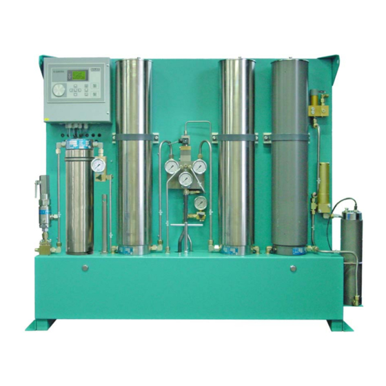
(see tive operation. flow diagram in the annex). To avoid excessive wear of the filter fillings, the SECCANT dry- ers are equipped with a pressure compensation system which Fig. 1 High pressure regenerative dryer SECCANT IV... -
Page 8: Fig. 2 Seccant Iv, Regenerative Dryer Design
For all mentioned parts and numbers refer to dryer design SEC- vents the dried medium from flowing back to the separator when CANT IV, Fig. 2 and SECCANT IV A, Fig. 3. draining condensate. The regenerative dryer consists of two filters (1 and 2), which For breathing air processing, a final purifier (27, Fig. -
Page 9: Fig. 3 Seccant Iv A, Regenerative Dryer Design
11 Safety valve, 14 bar 20 Condensate drain valve Fig. 3 SECCANT IV A, regenerative dryer design Particle filter (24) is placed downstream of the drying and regen- drying phase, a compensation of pressure takes place in the re- erating filters/the final purifier. After the filters, a pressure re- generating filter. - Page 10 Instruction Manual SECCANT IV TECHNICAL DATA Operating pressure, max. (Setting pressure of safety valve) 90 − 350 bar (2,175 − 5,000 psi) Flow rate at 200 bar 1500−3500 l/min. (53 − 124 c.f.m.) Regeneration volume related to 1 bar absolute (equiv. to 5% of delivery) 75 −...
-
Page 11: Function
The following position numbers refer to stan- Non−return valve (6) prevents high pressure air or gas coming dard air flow diagram SECCANT IV, Fig. 4. For from drying filter from entering the regeneration circuit. Pres- detailed information, also see air flow dia- sure gauge (27) indicates the pressure in the regenerated filter. - Page 12 Instruction Manual SECCANT IV PNEUMATIC CONTROL The air or gas needed to regenerate the filter and to control the pressure compensation, the switch−over and the condensate drain, is regulated by pressure reducer (11). The pressure is approx. 10 bar. Regeneration The air or gas needed for regeneration flows through regulating valve (13) and non−return valve (5) into the regenerating filter...
-
Page 13: Fig. 4 Standard Flow Diagram, Example Seccant
FLOW DIAGRAM A = Inlet B = Outlet C = Condensate outlet D = Regeneration outlet Fig. 4 Standard flow diagram, example SECCANT IV High pressure filter 30 4/2−way solenoid valve High pressure filter 31 Non−return valve Non−return valve 32 Discharge valve with pressure gauge Non−return valve... -
Page 14: Fig. 5 Controls And Monitors
Instruction Manual SECCANT IV B−CONTROL UNIT GENERAL The red and yellow LED’s next to the display indicate fault and warning messages. The details for the message are shown on BAUER B−CONTROL is a free−programmable electronic the display. The red LED indicates a compressor failure, and the compressor control system with a modern display. -
Page 15: Fig. 6
Instruction Manual SECCANT IV MENU AND NAVIGATION The 8−line, 21−digit display contains all the important S E C C A N T information on the present condition of your BAUER unit. Normally, the start page is displayed which shows the most F1: flush important general data in a very clear presentation. -
Page 16: Fig. 10 Operation Menue
Instruction Manual SECCANT IV main menu. A new entry may be tried now. The number of attempts is not limited. With higher priority (level) codes you will automatically get access to all lower priority levels, also, e.g. with the code for the... -
Page 17: Fig. 12 Filter Parameters
Instruction Manual SECCANT IV Filter parameters Fiter regeneration **** PARAMETERS **** This parameter sets the time periods for filter change−over, and filter / regeneration pressure balance. The factory setting is 15 minutes and 40 seconds. intervall 15 min balance 40 sec Fig. -
Page 18: Fig. 16 Maintenance Data Page
Instruction Manual SECCANT IV MAINTENANCE LEVEL The maintenance level is accessible after prompting the correct access code. At first you will come upon the maintenance data **** MAINTENANCE **** window: [2368 h] The difference now is that there will be a cursor which enables you to jump to additional pages. -
Page 19: Fig. 20 Filter Housing Service Data Page
Instruction Manual SECCANT IV By consecutively pressing the menu key, you can browse through the different maintenance pages. * MAINTENANCE-INTVL.* Direct selection from the maintenance menu is also possible. Filter housing Actual runtime: 784 x10 Cycl Target runtime 2000 x10 Cycl Reset >... -
Page 20: Fig. 24 Configuration Page
Instruction Manual SECCANT IV CONFIGURATION LEVEL The configuration level allows basic adjustments to be changed. Because of the possibility to change also values *** CONFIGURATION *** concerning the warning and safety adjustments, this level is accessible only with a special code. -
Page 21: Fig. 28 Control Voltage Transformer
Instruction Manual SECCANT IV Initialization RESETTING THE DEFAULT VALUES To reset the B−Control to the default settings, press and hold the code and reset keys while switching on the main switch. After a short period, while still pressing the code and reset keys, you will be asked if you want to select the default settings. - Page 22 Instruction Manual SECCANT IV Technical data Processor Motorola 68332 512 kB flash memory (zero voltage protected) Memory 512 kB RAM 256 kB EE−PROM configuration memory (zero voltage protected) Serial interface RS232 max.19200 Baud 9 pole D−Sub plug (male) CAN interface CAN High−Speed ISO DIS 11898...
-
Page 23: Installation, Operation
Instruction Manual SECCANT IV INSTALLATION, OPERATION INSTALLATION the dryer at a constant level to ensure continuous operation and drying process. Install regenerative type dryer according to Fig. 29. Electrical connection of the dryer must be carried out by a spe- For maintenance purpose, shut−off valves (2) have to be pro-... -
Page 24: Inspection And Maintenance
Weekly or as required Check automatic condensate drain; open manual condensate drain tap 1000 operating hours Change purifier cartridge (SECCANT IV A, only) 2000 operating hours Change both drying cartridges Change separator’s coalescent filter cartridge Change particle filter cartridge after max. -
Page 25: Fig. 30 Cartridge Change
Instruction Manual SECCANT IV CARTRIDGE CHANGE The activated charcoal cartridge of the purifier requires mainte- nance every 1,000 operating hours, the drying cartridges have to be changed every 2,000 operating hours. − Depressurize system completely and disconnect from elec- trical supply. -
Page 26: Fig. 31 Oil And Water Separator
Instruction Manual SECCANT IV MAINTENANCE OF PRESSURE VESSELS Oil and water separator The coalescent filter micro−cartridge of the oil and water sepa- rator requires maintenance every 2,000 operating hours or at least annually. To remove the cartridge proceed as follows (see Fig. 31): −... -
Page 27: Fig. 32 Particle Filter
Instruction Manual SECCANT IV Final purifier (on SECCANT IV A) The final purifier is equipped with a cartridge filled with activated charcoal. The cartridge has to be replaced every 1,000 operat- ing hours. To do so, depressurize system completely by dis- charge valve (28, Fig. -
Page 28: Trouble−Shooting
Instruction Manual SECCANT IV TROUBLE−SHOOTING Trouble Cause Remedy Excessive humidity of dried air/gas Dryer does not switch from drying to Check switch−over valve and/or regeneration due to defective control circuit and replace if neces- switch−over valve sary Desiccant in cartridge overaged... - Page 29 Instruction Manual SECCANT IV ANNEX Schematic diagrams, standard Air flow diagrams, standard Drawings Parts lists, standard or, depending on order Special documentation Schematic diagrams Air flow diagrams Illustrations Parts lists This special documentation supersedes and/or supplements the respec-...
- Page 30 Instruction Manual SECCANT IV...
Need help?
Do you have a question about the SECCANT IV and is the answer not in the manual?
Questions and answers