Advertisement
Quick Links
BY
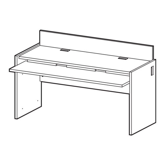
LW60
LAB WORKSTATION
I M P O R TA N T !
Assembly may require the assistance of
another person.
Before you begin assembly:
READ THE DIRECTIONS all the way through one
time. This will speed up the process and help you
understand the sequence of steps.
COUNT THE PARTS AND HARDWARE before
assembly. This ensures you have received all
necessary parts before you begin.
TOOLS: You may need a Phillips head screwdriver,
a medium slotted screwdriver or a plastic mallet. To
protect your new furniture from damage during
assembly, it is recommended to work on a
carpeted surface.
03/07
In the event any parts are missing from
this package, send your name, address,
telephone number, and a description of
the missing part(s) to: PARTS, Box 1420,
Missoula, MT 59806 or call:
1-800-769-5693 or FAX 1-800-445-5281.
CAUTION: On assemblies requiring glue, make
sure the unit is assembled correctly before gluing.
Once this unit is assembled with glue, the
manufacturer will not be responsible for damaged
parts. Keep a damp cloth or sponge handy to wipe
off excess glue.
To care for this furniture, simply wipe with a cloth
dampened with glass cleaner containing ammonia-D.
Advertisement

Subscribe to Our Youtube Channel
Related Manuals for Ironwood GLACIER LW60


Summary of Contents for Ironwood GLACIER LW60
- Page 1 LW60 LAB WORKSTATION I M P O R TA N T ! In the event any parts are missing from Assembly may require the assistance of this package, send your name, address, another person. telephone number, and a description of Before you begin assembly: the missing part(s) to: PARTS, Box 1420, Missoula, MT 59806 or call:...
-
Page 2: Parts Diagram
PARTS DIAGRAM Left Side 06001941 1 ea. Right Side 06001941 1 ea. 06002001 1 ea. Back 06002052 1 ea. Keyboard 06002028 1 ea. Drop Panel 06001981 3 ea. - Page 3 HARDWARE Minifix Cam 909810 24 ea. Minifix Bolt 909834 24 ea. Wood Dowel 195000 18 ea. Leveler Insert 274650 4 ea. Leveler 300870 4 ea. Confirmat Screw 950100 6 ea. Large Hex 999995 1 ea. Wrench Wire Trough 412990 2 ea. Grommet 286580 4 ea.
- Page 4 Using the Minifix System: Insert the Minifix Cams into the appropriate holes with the arrow facing outwards as shown. When screwing post into hole, Do Not over tighten. Screw post down until bottom face of post flange just touches board surface. ASSEMBLED DISASSEMBLED Using the #2 Phillips screwdriver,...
- Page 5 Insert eight Minifix Cams (H1) into the Top (C) with the arrows of the cams facing out. Screw six Minifix Bolts (H2) and insert six Dowels (H3) into the pre-drilled holes in the underside of the Top where indicated. Insert the Leveler Inserts (H4) into the holes in the bottom edges of Left Side (A) and Right Side (B).
- Page 6 Position the three Drop Panels (F) onto the posts and dowels of the Top (C) as shown. Turn the cams (H1) clockwise to secure in place. Position the Top (C) onto the Back (D) as shown Position the Top (C) and Back (D) assembly and turn cams (H1) clockwise to secure.
- Page 7 # 10 Position the Keyboard Shelf (K) onto Secure the Keyboard Shelf (K) to the the Left Side (A) as shown and turn Drop Panel (F) using six Confirmat cams (H1) clockwise to secure. Screws (H6) in the pre-drilled holes as shown.
- Page 8 # 12 Peel the paper backing off of the adhesive strip on the Wire Trough (H8). Attach the Wire Trough to the Back of the unit and secure in place by driving two Panhead Screws (H10) through the predrilled holes in the Wire Trough. Note: It will be difficult to remove or reposition the wire trough once the Back and Top are joined.
- Page 9 CONNECTING OTHER WORKSTATIONS: Remove Grommets from the panels to be connected. Using a 13/64" bit, drill through the four pilot holes on the inside of each side panel. Align the side panels of the units to be connected. Tap four Connector Sleeves (H10) through the holes in one side panel and into the holes of the unit to be connected.
Need help?
Do you have a question about the GLACIER LW60 and is the answer not in the manual?
Questions and answers