Solplanet SOL APOLLO Series User Manual
Smart ev charger
Hide thumbs
Also See for SOL APOLLO Series:
- User manual (52 pages) ,
- Quick installation manual (135 pages)
Table of Contents
Advertisement
Quick Links
Advertisement
Table of Contents

Related Manuals for Solplanet SOL APOLLO Series


Summary of Contents for Solplanet SOL APOLLO Series
- Page 2 Thank you for choosing our Solplanet Smart EV Charger. The Solplanet Smart EV Charger is an AC power charging station, it supplies AC power to cargers: SOL7.4H, SOL11H, SOL22H. Please read and follow the instructions in this manual carefully. UM0027_ SOL APOLLO Series 7.4-22K_EN_V02_0523...
-
Page 3: Table Of Contents
4.4 Interfaces ....................27 4.5 Special Features ..................28 5 Mounting ....................... 29 5.1 Planning the Installation ................ 29 5.2 Site Requirements ................. 29 5.3 Selecting the mounting location ............31 5.4 Mounting the product ................31 UM0027_ SOL APOLLO Series 7.4-22K_EN_V02_0523... - Page 4 9.1 Inputs and Outputs (AC) ............... 57 9.2 General data ..................58 9.3 Safety regulations .................. 60 9.4 Wireless network specifications ............61 10 Recycling and disposal ................62 11 EU declaration of conformity ..............62 12 Contacts ..................... 63 UM0027_ SOL APOLLO Series 7.4-22K_EN_V02_0523...
-
Page 5: Notes On This Manual
1 Notes on this Manual General Notes The Solplanet Smart EV Charger is an AC power charging station, it supplies AC power to charge electric vehicles. 1.1 Area of validity This manual describes the mounting, installation, commissioning, operation and maintenance of the following SOL APOLLO EV chargers: ⚫... -
Page 6: Symbols Used In This Manual
NOTICE indicates a situation which, if not avoided, can result in property damage. INFORMATION provides tips which are valuable for the optimal installation and operation of the EV charger. UM0027_ SOL APOLLO Series 7.4-22K_EN_V02_0523... -
Page 7: Terms And Definitions
Bluetooth Low Energy Emergency Power Supply RFID Radio Frequency Identification WLAN Wireless Local Area Networks Near Field Communication Control pilot, used to monitor and control the interaction between the EV and the EV supply equipment. UM0027_ SOL APOLLO Series 7.4-22K_EN_V02_0523... -
Page 8: Safety
Guide are fully understood. Failure to follow all the specified instructions and procedures, will invalidate the warran- ty and as such Solplanet will not be liable for any claims for compensation. UM0027_ SOL APOLLO Series 7.4-22K_EN_V02_0523... - Page 9 • No modifications, not limited to mechanical or electrical, must be made to the EV charger. • Components should not be changed or replaced by the end-user or unqualified personnel. • Do not use conversion adapters or cord extension sets with the EV charger. UM0027_ SOL APOLLO Series 7.4-22K_EN_V02_0523...
-
Page 10: Symbols On Label
The EV charger provides the following safety protection functions: 1) Over-voltage, under-voltage protection; 2) Over-frequency, under-frequency protection; 3) Over-current protection; 4) Residual current monitoring; 5) Grounding conductor monitoring; 6) Relay fault monitoring; 7) Phase lost monitoring; 8) Over-temperature monitoring. UM0027_ SOL APOLLO Series 7.4-22K_EN_V02_0523... -
Page 11: Scope Of Delivery
ST3×10mm screw (×2) Mounting template 1 piece RFID card 3 pieces AC Input cable fastener 1 piece Energy meter (Optional) 1 piece Cable holder (for cable version) 1 piece Quick installation guide 1 piece Sheet 3 UM0027_ SOL APOLLO Series 7.4-22K_EN_V02_0523... -
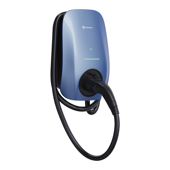
Page 12: Overview
Area for RFID card scanning or for use with NFC authorized smart devices. LED strip Indicates the operating state of the EV charger. Socket Input cable gland Communication cable gland Type label QR code Knockout entry reserved for input AC cable. UM0027_ SOL APOLLO Series 7.4-22K_EN_V02_0523... - Page 13 Area for RFID card scanning or for use with NFC authorized smart devices. LED strip Indicates the operating state of the EV charger. Charging plug Input cable gland Communication cable gland Type label QR code Charging plug cable UM0027_ SOL APOLLO Series 7.4-22K_EN_V02_0523...
-
Page 14: System Overview With Power Management
EV charger charging power will increase accordingly. The increase of power will be no greater than 32A and can be also limited by the EV on-board charger (OBC). And the system overview in different application are like the pictures below: UM0027_ SOL APOLLO Series 7.4-22K_EN_V02_0523... - Page 15 System Overview with EV-Charger Only EV Charger DLB Figure 3 UM0027_ SOL APOLLO Series 7.4-22K_EN_V02_0523...
- Page 16 EV Charger DLB Figure 4 UM0027_ SOL APOLLO Series 7.4-22K_EN_V02_0523...
- Page 17 System Overview with EV-Charger and Ongird Inverter EV Charger DLB Ongrid inverter 0-export Figure 5 UM0027_ SOL APOLLO Series 7.4-22K_EN_V02_0523...
- Page 18 EV Charger DLB Ongrid inverter 0-export Figure 6 UM0027_ SOL APOLLO Series 7.4-22K_EN_V02_0523...
- Page 19 EV Charger DLB Ongrid inverter 0-export Figure 7 UM0027_ SOL APOLLO Series 7.4-22K_EN_V02_0523...
- Page 20 System Overview with EV-Charger and Hybrid Inverter EV Charger DLB Hybrid inverter 0-export Figure 8 UM0027_ SOL APOLLO Series 7.4-22K_EN_V02_0523...
- Page 21 EV Charger DLB Hybrid inverter 0-export Figure 9 UM0027_ SOL APOLLO Series 7.4-22K_EN_V02_0523...
- Page 22 System Overview with EV-Charger, Hybrid and Ongird Inverter EV Charger DLB Hybrid inverter 0-export Ongrid inverter 0-export Figure 10 UM0027_ SOL APOLLO Series 7.4-22K_EN_V02_0523...
- Page 23 EV Charger DLB Hybrid inverter 0-export Ongrid inverter 0-export Figure 11 UM0027_ SOL APOLLO Series 7.4-22K_EN_V02_0523...
- Page 24 EV Charger DLB Hybrid inverter 0-export Ongrid inverter 0-export Figure 12 UM0027_ SOL APOLLO Series 7.4-22K_EN_V02_0523...
- Page 25 AISWEI. The Ai-Dongle supports Ethernet communication and WLAN communication. It is not recommend- Ai-Dongle ed to use both communication methods at the same time. UM0027_ SOL APOLLO Series 7.4-22K_EN_V02_0523...
- Page 26 The monitor information is stored at cloud server. server Smart The APP can be installed on the smart phone phone and then review the monitor information. The monitor information also can be review on Computer the computer. Ai-charger APOLLO EV Charger. UM0027_ SOL APOLLO Series 7.4-22K_EN_V02_0523...
-
Page 27: Led Indicators
Purple - blinking Firmware update RFID card identification succeeded (with Ice blue - blinking (once) operation) Ice blue - blinking (twice) RFID card binding succeeded RFID card identification succeeded (without Purple - blinking (once) operation) UM0027_ SOL APOLLO Series 7.4-22K_EN_V02_0523... -
Page 28: Interfaces
EV charger and a smart mobile device. Ethernet (optional) The EV charger is supplied with Solplanet Speedwire as optional configura- tion, which is a type of communication based on the Ethernet standard. Sol- planet Speedwire is designed for a data transfer rate of 100 Mbps and enables optimum communication between the EV charger and the Ai-charging app via a router. -
Page 29: Special Features
EV charger may prioritise the use of excess solar power generated by a PV system, if available, rather than the grid power. UM0027_ SOL APOLLO Series 7.4-22K_EN_V02_0523... -
Page 30: Mounting
2. Ensure appropriate access to the product for installation and maintenance. 3. Ensure there is adequate heat dissipation by observing the minimum clearance to walls, other EV chargers or objects: Direction Min. Clearance (mm) above below sides UM0027_ SOL APOLLO Series 7.4-22K_EN_V02_0523... - Page 31 9. If mounted in a residential area, we recommend mounting the product on a solid surface. Plasterboard and similar materials are not recommended. 10. Do not place any objects on the product. UM0027_ SOL APOLLO Series 7.4-22K_EN_V02_0523...
-
Page 32: Selecting The Mounting Location
5. The electrical connection area must point downwards. 5.4 Mounting the product Removing the decorative cover Remove the bottom screw (A) on the flat workbench. It is recommended to start at the bottom of enclosure (C) when removing the decorative cover (B). UM0027_ SOL APOLLO Series 7.4-22K_EN_V02_0523... - Page 33 2. Mark the location for three mounting holes (B). 3. Drill three mounting holes (B). 4. Insert the wall plugs (C) into the mounting holes (B). Figure 14 UM0027_ SOL APOLLO Series 7.4-22K_EN_V02_0523...
- Page 34 The length of (X) is recommended to be 3mm (0.12inch). Figure 15 Installing the EV charger on the wall 1. Align the openings (A) over the upper mounting screws (B). The upper mounting screws support the EV charger. Figure 16 UM0027_ SOL APOLLO Series 7.4-22K_EN_V02_0523...
- Page 35 Installing the inner screw on the bottom cover Thread the screw (A) through the sealing rubber (B). Then install the mounting screw (A) to secure the enclosure to the surface. The recommended torque is 4.4Nm. Figure 18 UM0027_ SOL APOLLO Series 7.4-22K_EN_V02_0523...
- Page 36 Option 1: Through the cable gland (A) located on the bottom of the enclosure. Figure 19 Option 2: Drilling a hole through the rubber seal located on the rear of the enclosure (A). Figure 20 UM0027_ SOL APOLLO Series 7.4-22K_EN_V02_0523...
- Page 37 Copper conductor cross- 4-16mm section Stripping length of the 12mm insulated conductors Stripping length of the 75mm cable outer sheath Note: the PE conductor is at least 5mm longer than the L and N conductors. UM0027_ SOL APOLLO Series 7.4-22K_EN_V02_0523...
- Page 38 2. Install the incoming AC supply cable Option 1 Remove the cable gland from the bottom of the enclosure. Figure 21 Thread the incoming AC supply cable through the cable gland, loosen the nut (A). Figure 22 UM0027_ SOL APOLLO Series 7.4-22K_EN_V02_0523...
- Page 39 Install the cable gland on the bottom of the enclolsure, fasten the nut (B) and then fasten the nut (A). Figure 23 Option 2: According to the diameter of the incoming AC supply cable, select the appropriate circle on the rubber seal to penetrate. Figure 24 UM0027_ SOL APOLLO Series 7.4-22K_EN_V02_0523...
- Page 40 Thread the input cable through the rubber. Figure 25 Install the rubber seal (A) on the rear of the enclosure (B). Figure 26 UM0027_ SOL APOLLO Series 7.4-22K_EN_V02_0523...
- Page 41 Three phase Loosen the cable clamps (A) of the terminal block. Insert cable into the terminal block (B). Connect the below wires: Line L1 (C) Line L2 (F) Line L3 (G) Neutral (D) Grounding (E) UM0027_ SOL APOLLO Series 7.4-22K_EN_V02_0523...
- Page 42 31, and crimp the copper wire to the appropriate OT terminal (according to DIN 46228-4, provided by the customer) if the cable is multi strand flexible conductor. The other end of the cable should be connected UM0027_ SOL APOLLO Series 7.4-22K_EN_V02_0523...
- Page 43 Sheet 11 Name Description RS-485A-1 For communication with an energy meter RS-485B-1 RS-485A-2 For communication with an energy meter RS-485B-2 2. Remove the middle cable gland (A) at the bottom of the enclosure. Figure 32 UM0027_ SOL APOLLO Series 7.4-22K_EN_V02_0523...
- Page 44 4. Assemble the cable gland and loosen the external nut (A). Figure 34 5. Install the cable gland at the bottom of the enclosure and fasten the nut (B), afterwards fasten the nut (A). Figure 35 UM0027_ SOL APOLLO Series 7.4-22K_EN_V02_0523...
- Page 45 RS-485 cable in the RS-485 socket (B). Figure 36 Insert 4G SIM card (optional) Insert the SIM card (A) into the sim card holder (B). Ensure the position of the connection points are correct. Figure 37 UM0027_ SOL APOLLO Series 7.4-22K_EN_V02_0523...
- Page 46 It is recommended to start at the bottom of the enclosure (C) when removing the decorative cover (B). Figure 38 Installing the decorative cover Install the following parts: Screw (A) Decorative cover (B) Figure 39 UM0027_ SOL APOLLO Series 7.4-22K_EN_V02_0523...
- Page 47 Removing the top cover Remove the following parts: Screws (A) Top cover (B) Figure 40 Installing the top cover Install the following parts: Screw (A) Top cover (B) The recommended torque is 0.8Nm. Figure 41 UM0027_ SOL APOLLO Series 7.4-22K_EN_V02_0523...
-
Page 48: Commissioning And Operation
If the AC input cable neutral line is connected opposite to the L line, the EV charger will become damaged due to the higher voltage. Figure 42 ③ Ensure the communication cable has been correctly wired and secured. ④ Ensure the cable gland has been correctly installed and secured. UM0027_ SOL APOLLO Series 7.4-22K_EN_V02_0523... -
Page 49: Electrical Checks
6.4 Activate the RFID card Requirement: The EV charger should be powered on, and the charging cable disconnected from the electric vehicle. ① Place RFID card in the front of the card reader on the EV charger. UM0027_ SOL APOLLO Series 7.4-22K_EN_V02_0523... -
Page 50: Charging Ev
Wait for 5s, and the EV charger will unlock the charging cable connector auto- matically. ② Start the EV charger with the Ai-charging app or RFID card. ③ The EV charger begins charging the electric vehicle. Figure 43 UM0027_ SOL APOLLO Series 7.4-22K_EN_V02_0523... - Page 51 Wait for 5s, and the EV charger will unlock the charging cable connector automatically. ② Start the EV charger with the Ai-charging app or RFID card ③ The EV charger begins charging the electric vehicle. Figure 44 UM0027_ SOL APOLLO Series 7.4-22K_EN_V02_0523...
-
Page 52: Stop Charging
5s, and the EV charger will unlock the charging cable connector automa- tically. ③ Disconnect the charging cable from the electric vehicle, the colour of the EV charger LED strip changes from ice blue to green. ④ Wrap the charging cable around the enclosure. Figure 45 UM0027_ SOL APOLLO Series 7.4-22K_EN_V02_0523... - Page 53 ③ Disconnect the charging cable from the electric vehicle, the colour of the EV charger LED strip changes from ice blue to green. ④ The EV charger unlocks the charging cable. ⑤ Disconnect the charging cable from the EV charger. Figure 46 UM0027_ SOL APOLLO Series 7.4-22K_EN_V02_0523...
-
Page 54: Cleaning And Maintenance
• Wait approx. 10 minutes before cleaning until the enclosure is cool enough to touch. • Ground yourself before touching any component. The charging cable must be regularly checked for any damage or deteriora- tion. Figure 47 UM0027_ SOL APOLLO Series 7.4-22K_EN_V02_0523... -
Page 55: Troubleshooting
The EV charger 275V. If it is not within this Blinking - 4 times detects that the supply range, please contact your voltage is too low. local electricitiy supplier. If it is within this range, please UM0027_ SOL APOLLO Series 7.4-22K_EN_V02_0523... - Page 56 EV charger is too high or Blinking - 12 detects an whether it is exposed to times overtemperature fault. direct sunlight. Please stop charging for a few hours and wait for the temperature of UM0027_ SOL APOLLO Series 7.4-22K_EN_V02_0523...
- Page 57 Blinking - 15 within this range, please detects an under- times contact your local electricitiy frequency fault. supplier. If it is within this range, please contact the Solplanet service provider. Please contact the Solplanet others service provider. UM0027_ SOL APOLLO Series 7.4-22K_EN_V02_0523...
-
Page 58: Technical Data
Rated AC input voltage 230V 400V AC power frequency 50/60Hz Standby power consumption <5W Max. output current Max. output overcurrent 35.2A 17.6A 35.2A protection Conductor cross-section, rigid 3x6mm² 5x6mm² or flexible 3x10mm² 5x10mm² Conductor cross-section, rigid UM0027_ SOL APOLLO Series 7.4-22K_EN_V02_0523... -
Page 59: General Data
5m/7.5m Cable Length ● Morandi Blue / ● Black Color Remark: ● Standard features / 〇 optional features / – not available 1) LAN is optional 2) Self-closing cover and built-in electronic lock is standard UM0027_ SOL APOLLO Series 7.4-22K_EN_V02_0523... - Page 60 Optional energy meter is needed or must be installed for solar charging function and Dynamic Load Balancing. Type2 Plug Type2 Socket with Shutter Type2 Socket Figure 48 The Shutter version socket connector has a shutter on the conductor pins to prevent accidental contact. UM0027_ SOL APOLLO Series 7.4-22K_EN_V02_0523...
-
Page 61: Safety Regulations
Residual Current Type A: AC 30mA / DC 6mA Detection ● DC Leakage Protection Surge Protection ● (Type III) (EN60664) Certification CE, TUV/EN/IEC 61851-1 Overvoltage category III(AC) Over current Over/Under Voltage Integrated Ground fault Over temperature UM0027_ SOL APOLLO Series 7.4-22K_EN_V02_0523... -
Page 62: Wireless Network Specifications
TX:880.2 – 914.8MHz 4G GSM 900 1800mW RX:925.2 – 959.8MHz TX:1710.2 – 1784.8MHz 4G GSM 1800 950mW RX:1805.2 – 1879.8MHz TX/RX:2412 – 2484MHz Wifi module 90mW TX/RX:2402 – 2480MHz BT module Receive Distance : NFC module TX/RX:13.56MHz UM0027_ SOL APOLLO Series 7.4-22K_EN_V02_0523... -
Page 63: Recycling And Disposal
EV chargers mentioned in this document are in compliance with the fundamental requirements and other relevant provisions of the above mentioned directives. The entire EU Declaration of Conformity can be found at www.solplanet.net. UM0027_ SOL APOLLO Series 7.4-22K_EN_V02_0523... -
Page 64: Contacts
You can submit your claims online by visiting website: https://solplanet.net/claims/ You will receive a response within 24 hours. AISWEI New Energy Technology (Yangzhong) Co., Ltd. Add.: No.588 Gangxing Road, Yangzhong Jiangsu, China Web: https://solplanet.net UM0027_ SOL APOLLO Series 7.4-22K_EN_V02_0523... - Page 65 UM0027_ SOL APOLLO Series 7.4-22K_EN_V02_0523...
Need help?
Do you have a question about the SOL APOLLO Series and is the answer not in the manual?
Questions and answers