Table of Contents
Advertisement
Quick Links
Advertisement
Table of Contents

Summary of Contents for OptoSigma TM-2070
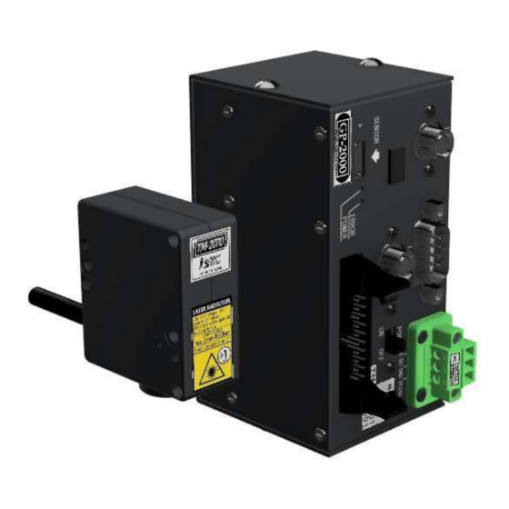
- Page 1 Compact type Tilt Sensor TM-2070 + GP-2000 Operation Manual...
-
Page 2: Table Of Contents
......................8 3-3 Sensor cable ......................8 4 Mounting· setting· Connection ................9 4-1 Mounting ........................9 4-1-1 Installation of compact type Tilt Sensor(TM-2070)............9 4-1-2 Installation of image processing unit(GP-2000) ............9 4-2 setting ........................10 4-3 Connection ......................11 4-3-1... -
Page 3: 1 Read This First
10-2 Input and output circuit characteristics ............... 36 10-3 Timing chart ......................36 11 Dimensions ....................... 37 11-1 Compact type Tilt Sensor TM-2070 ..............37 11-2 Image processing unit GP-2000 ................37 11-3 Sensor cable KE-0059..................38 11-4 Sensor cable KE-0060..................38 12... - Page 4 ● Turn off the power to the equipment immediately when foul smell and smoke are detected or when the laser does not turn on. Remove the cause before operating the equipment again. Operation Manual 4 / 49 TM-2070 CTS0358E 3ed Edition 220518...
-
Page 5: Overview
This product uses an optical autocollimator to measure the tilt(θx、θy)of an object. Connecting to Image Processing Unit , it is possible to output and evaluate the measurement result. 1-2-2 Specifications Compact type tilt sensor TM-2070 Measurement object Optical flat mirror(Reflectivity over 0.5%) Working distance 0~110mm ※1... - Page 6 Pin Number Signal Recommended wire size ※5 Power supply ※4 ) Pin No.1 DC24V AWG24~16(0.2~1.25mm Wiring ) Pin No.2 DC_GND AWG24~16(0.2~1.25mm ) Pin No.3 AWG18~16(0.75~1.25mm Environment Operating temperature range 0~40℃ ※6 Operation Manual 6 / 49 TM-2070 CTS0358E 3ed Edition 220518...
-
Page 7: 2 System Configuration
Specification Compact type Tilt Sensor /TM-2070 Refer to「1-2-2 Specification」 Image Processing Unit /GP-2000 Refer to「1-2-2 Specification」 Sensor cable /KE-0059 TM-2070/GP-2000 Special cable 1m Type-C Connector ※1 Power connector /FH-0022 GP-2000 power terminal(Phoenix Contact:1827716) Operation Manual 7 / 49 TM-2070 CTS0358E 3ed Edition 220518... -
Page 8: 3 Names And Function Of Each Part
For GP-2000 AC adapter /FH-0023 For DC24V GP-2000 Sensor cable /KE-0060 TM-2070/GP-2000 Special cable 2m Type-C Connector USB cable /KE-0014 Cable for USB2.0 A connector- Mini B connector 2m 3 Names and function of each part 3-1 Compact type Tilt Sensor... -
Page 9: Head Part
[ Cable lock mechanism department ] TM - 207 0 and GP - 2000 Unit are used in a pair. Do not change the combination. [ Sensor cable ] connector Operation Manual 9 / 49 TM-2070 CTS0358E 3ed Edition 220518... -
Page 10: Processing Unit
(The laser is not on/The brightness of sensor camera is below PK50 / No laser beam in the measurement range and POWER green light flashes so on) ERROR red light flashes The power is on but TM-2070 and GP-2000 are not normally connected(ER Status). ERROR red light ER status other than the above(red light flashes). Operation Manual... -
Page 11: 3-3 Sensor Cable
[ Arrow mark ] 4 Mounting· setting· Connection 4-1 Mounting 4-1-1 Installation of compact type Tilt Sensor(TM-2070) Two M3 tap holes for mounting on one side of the head part and two φ3.2 through-holes are provided. (Refer to Dimension) Use screws with thread length over 3mm and below 5mm. - Page 12 ※Option 4-2 setting Place the TM-2070 head section so that the object will be irradiated with laser. (About the details of dimensions , please refer to "9 dimensions.") The distance between measurement object and head part (WD: working distance) is 0 to 110 mm ( Meet each specification value ) . It can be used even more than 110 mm, but it becomes outside of each specification value, and when the WD becomes long, the measurement field is reduced.
- Page 13 In order to prevent the effect of vibration, choose a strong installation place(Around the pillars and walls), or Equipment with sufficient strength. We recommend that you install it on the Shockproof platform. 4-3 Connection Operation Manual 13 / 49 TM-2070 CTS0358E 3ed Edition 220518...
-
Page 14: Connection Diagram
PC, etc ( to get Camera image) PC, etc ① ⑥ ( F or RS - C communication ) ② ⑦ ③ ⑤ ※ Option External equipment ④ DC24V power supply Operation Manual 14 / 49 TM-2070 CTS0358E 3ed Edition 220518... -
Page 15: Connection Of Compact Type Tilt Sensor(Tm-2070)And Sensor Cable(Ke-0059/60)12
4-3-2 Connection of Compact type Tilt Sensor(TM-2070)and sensor cable(KE-0059/60) The connector part of the compact type Tilt Sensor is connected to the cable connector marked「TM-2070」. Connect the face marked with arrow mark, fix the cable locking mechanism with the attached screw after connection. -
Page 16: Rough Flow Until The Beginning Of Measurement
[GP-2000 Paramset] Disp tab screen the spot brightness to the appropriate value. Head PC ※1 Object DC24V Power There are three ways to adjust: The suitable brightness range is the range of PK120~240. Operation Manual 16 / 49 TM-2070 CTS0358E 3ed Edition 220518... -
Page 17: 6 Power On And Off
Explanation of each procedure and PC software[GP-2000 Paramset], serial command, etc. follow the nect chapter. 6 Power on and off 6-1 Power on procedure While GP-2000 supplies power, Imaging device of TM-2070 works. The laser turns on when the power is turned on by parameter setting. (1)... -
Page 18: 7 Start Software[Gp-2000 Paramset]
(5)Copy [GP-2000 paramset] from your CD-ROM to your PC's hard disk and start the software. (6)Select COM port and baud rate for serial communication and press OK button to start the software. Operation Manual 18 / 49 TM-2070 CTS0358E 3ed Edition 220518... -
Page 19: 8 Operation Method Of Software[Gp-2000 Paramset]
※It cannot be displayed without removing password protection. Display Displays the tilt measurement screen. ※How to remove password protection (1) Choose Option → Protection item → Remove protection from the menu. (2) Enter the password Password:katura Operation Manual 19 / 49 TM-2070 CTS0358E 3ed Edition 220518... -
Page 20: Basic Operation
Displays the unlock password dialog. protection Help About Displays the software version. Setting Set the measurement screen size and display unit. ※3 ③ Tilt Set tilt measurement and judgment, etc. Operation Manual 20 / 49 TM-2070 CTS0358E 3ed Edition 220518... -
Page 21: Parameter Setting Screen「Setting Tab
Set the measurement screen size of the display tab. If the unit is deg and the screen size is set to ±1deg, input 1. ① XY Range Factory setting:1.1667 Specify display unit. ② Unit Factory setting:min Operation Manual 21 / 49 TM-2070 CTS0358E 3ed Edition 220518... -
Page 22: Parameter Setting Screen「Tilt Tab
⑤ displayed here. ⑥ ⑩ ※ Except ⑮ ⑯ ⑦ ⑧ ⑯ ⑨ ⑰ ⑩ ⑱ ⑪ ⑳ ⑫ ⑲ ⑬ ㉑ ㉓ ㉒ ⑭ No. Display name Remarks Operation Manual 22 / 49 TM-2070 CTS0358E 3ed Edition 220518... - Page 23 Specifies the vertical width of the range. ⑦ Rectangle judgment If specified as±5minutes, specify「10」minutes. Height Factory setting:Values matching the connected sensor. Specifies the width of the range. Width Factory setting:Values matching the connected sensor. Operation Manual 23 / 49 TM-2070 CTS0358E 3ed Edition 220518...
- Page 24 Factory setting:Volume(%) Algorithm ⑯ After subtracting the threshold value (%) of the maximum brightness value from the whole screen, the volume centroid is determined and displayed as a Volume(%) measurement value. Operation Manual 24 / 49 TM-2070 CTS0358E 3ed Edition 220518...
- Page 25 Disable input from external I / O device. Enable Enable input from external I / O devices. ㉓ Working distance Enter the set WD. ※1 Measurement screen for measuring offset Operation Manual 25 / 49 TM-2070 CTS0358E 3ed Edition 220518...
- Page 26 Green (just right):120 <Max brightness ≦ 240 Mark color Yellow (near saturation):240 < Max brightness ≦ brightness value Yellow (near saturation):240 <Max brightness ≦ 250 Red (saturated):250 <Max brightness Red (saturated) :250 <Max brightness Operation Manual 26 / 49 TM-2070 CTS0358E 3ed Edition 220518...
- Page 27 To make it easy to understand, the following parameters are set up. Image rotation『None』 Image rotation『90[deg]』 Display rotation status Rotation of picture center Image rotation『-90[deg]』 Image rotation『180[deg]』 Image inversion『None』 Image inversion『Horizontal』 Operation Manual 27 / 49 TM-2070 CTS0358E 3ed Edition 220518...
- Page 28 【Meas. inversion】setting changes the measurement screen as follows. Meas. inversion『None』 Meas. inversion『Horizontal』 X sign is inverted The folding line passes through the center of the screen Meas. inversion『Vertical』 Meas. inversion『Both』 Operation Manual 28 / 49 TM-2070 CTS0358E 3ed Edition 220518...
-
Page 29: Parameter Setting Screen「Apc Tab
Y sign is inverted X and Y signs are inverted 8-5Parameter setting screen「APC tab」 ① ② ③ ④ ⑤ ⑥ ⑦ ⑧ ⑨ Operation Manual 29 / 49 TM-2070 CTS0358E 3ed Edition 220518... - Page 30 Sets interval for the APC operation. If the setting is 3, the power or shutter is changed, and the value after 3 frames is confirmed and the next control operation is transferred. ⑨ Apc int frame Factory setting:3 Operation Manual 30 / 49 TM-2070 CTS0358E 3ed Edition 220518...
- Page 31 Specifies the parity of the I / F-2 communication. Fixed ⑦ Parity value (none). Specifies the stop bit of the I / F-2 communication. Fixed ⑧ Stop bit value (1). Operation Manual 31 / 49 TM-2070 CTS0358E 3ed Edition 220518...
- Page 32 LD OFF/LD ON LD OFF Laser turned off. LD ON Laser turned on. Switch laser control mode. MANUAL ⑤ AUTO(CONT) MANUAL Adjust laser power and camera shutter mode manually. AUTO(HOLD) Operation Manual 32 / 49 TM-2070 CTS0358E 3ed Edition 220518...
- Page 33 About the set content ,check「8-4 Tilt tab(Tilt settings)」. No indication The state set to None Measurement inversion ⑭ status display The state set to Horizontal The state set to Vertical M-HV The state set to Both Operation Manual 33 / 49 TM-2070 CTS0358E 3ed Edition 220518...
- Page 34 A circle with radius【Triple circle Radius】centered on the center tilt of the judgment range. ㉖ Only draws and is not used for judgement. Triplet circle It draws only if【Triple circle】is「ON」. Operation Manual 34 / 49 TM-2070 CTS0358E 3ed Edition 220518...
-
Page 35: 9 Data Communication Function
Stop bit (Stop bit) Flow control None ※Issue a new command after receiving the response data, not issuing continuously. ※Keep a data interval within 1 second when sending each command. Operation Manual 35 / 49 TM-2070 CTS0358E 3ed Edition 220518... - Page 36 L(CR)(LF) Request continuous output of measurement data. sampling data ① *1: Specify output interval. Output all data in one、Output at once L,*1(CR)(LF) every two 、Output every two in three … Operation Manual 36 / 49 TM-2070 CTS0358E 3ed Edition 220518...
- Page 37 GETCON(CR)(LF) current value request *1 ,*2(CR)(LF) request」. Change the Unit. *1:0~5 OK(CR)(LF) 0:min、1:deg、2:mdeg、3:mrad、 Change Unit SETUNIT, *1(CR)(LF) 4:deg-min-sec、5:min-sec NG(CR)(LF) OK/Unit changed. NG/*1 out of the range, failed to change unit. Operation Manual 37 / 49 TM-2070 CTS0358E 3ed Edition 220518...
- Page 38 ※The transmission command 27 is enabled by the hardware reset (power ON→OFF→ON) when stored in the storage element with the 31 parameter Save command. ※The transmission commands 22, 24, 26, 28, 30 are managed on the RAM. The memory element is read once on the RAM at the time of hardware reset. Operation Manual 38 / 49 TM-2070 CTS0358E 3ed Edition 220518...
- Page 39 Tilt direction(DIR) is output. When ND、ER he numeric part is hyphen. *6 Judgment result The result is output by a string. ※Data format①B ・If the units are min、deg、mdeg、mrad 1, Unit, Tilt-X, Tilt-Y, Angle, Direction, Judge(CR)(LF) Operation Manual 39 / 49 TM-2070 CTS0358E 3ed Edition 220518...
- Page 40 Tilt composition value(ANG)is output. The Content based on tilt X. *5 Tilt direction Tilt direction(DIR)is output. When ND、ER he numeric part is hyphen. *6 Judgment result The result is output by a string. Operation Manual 40 / 49 TM-2070 CTS0358E 3ed Edition 220518...
- Page 41 ND character is output when ND. ER character is output when ER. *2 Tilt Y Tilt Y is output. The Content based on tilt X. ※Data format④ RA, *1, *2, *3, *4 (CR)(LF) Operation Manual 41 / 49 TM-2070 CTS0358E 3ed Edition 220518...
- Page 42 *3 Tilt Y Tilt Y is output. The Content based on tilt X. *4 Synthetic Tilt Synthetic Tilt(ANG)is output. The Content based on tilt X. Operation Manual 42 / 49 TM-2070 CTS0358E 3ed Edition 220518...
-
Page 43: O Terminal Function
Spare terminal for input. Preliminary input Spare terminal for input. Input COMMON (No.11 No.11、13、15、17 input COMMON. 、13、15、17) Name content READY output Output in measurable state. REL output Output when logging in relative origin. Operation Manual 43 / 49 TM-2070 CTS0358E 3ed Edition 220518... - Page 44 Output in error state. LD ON output Output when LD is on. GOOD output Output when camera brightness is in GOOD set range. Output COMMON COMMON for No.12、14、16、18 output. (No.12、14、16、18) Operation Manual 44 / 49 TM-2070 CTS0358E 3ed Edition 220518...
-
Page 45: Input And Output Circuit Characteristics
※The input signal should hold a SHORT state over 50ms continuously. ※The input signal will be disable if the Input settings in the parameter set screen [Tilt tab] is disable. Operation Manual 45 / 49 TM-2070 CTS0358E 3ed Edition 220518... -
Page 46: 11 Dimensions
M in 0.8 s econd SHORT READY OPEN M in 0.8 s econd SHORT SOFT RESE T OPEN 11 Dimensions 11-1 Compact type Tilt Sensor (autocollimator head) TM-2070 Overall dimension Laser warning seal UNIT : mm 11-2 Image processing unit GP-2000 Operation Manual... -
Page 47: Sensor Cable Ke-0059
Overall dimension UNIT:mm 11-3Sensor cable KE-0059 Overall dimension UNIT:mm Operation Manual 47 / 49 TM-2070 CTS0358E 3ed Edition 220518... -
Page 48: Sensor Cable Ke-0060
Warranty One-Year Limited Warranty including a one-way shipping cost, for a period of one (1) year from the date of shipment. period: Coverage: OptoSigma or Katsura Opto Systems warrants this product against defects in materials and workmanship under normal use for a period of one (1) year from the date of shipment. - Page 49 Operation Manual 49 / 49 TM-2070 CTS0358E 3ed Edition 220518...
Need help?
Do you have a question about the TM-2070 and is the answer not in the manual?
Questions and answers