Table of Contents
Advertisement
Quick Links
Advertisement
Table of Contents

Related Manuals for Mounting Systems Premium Series

Summary of Contents for Mounting Systems Premium Series
- Page 1 FD3-S Premium Line Installation Manual...
-
Page 2: Table Of Contents
Content Introduction Short description About these instructions Warning Safety Tools Basic information about system Elements and components Assembly Universal central and end support Front support Rear support Connecting rails End of the rail connection Rail layout Ballast tray Adapter wind deflector Assembly of modules and side covers 3.10 End clamp... -
Page 3: Introduction
10° or 15° as standard. The FD3-S system is documents, please contact Mounting Systems GmbH. built in connection with the total area of modules of at User group least 10 m . -
Page 4: Warning
The following warnings are used in these Installation All universally valid safety instructions for products of Instructions to indicate safety-related information. Mounting Systems GmbH are listed in the document They include: ‘Montageanleitung für PV-Gestellsysteme: allgemeiner Teil’ [“Installation manual for PV mounting systems –... -
Page 5: Basic Information About System
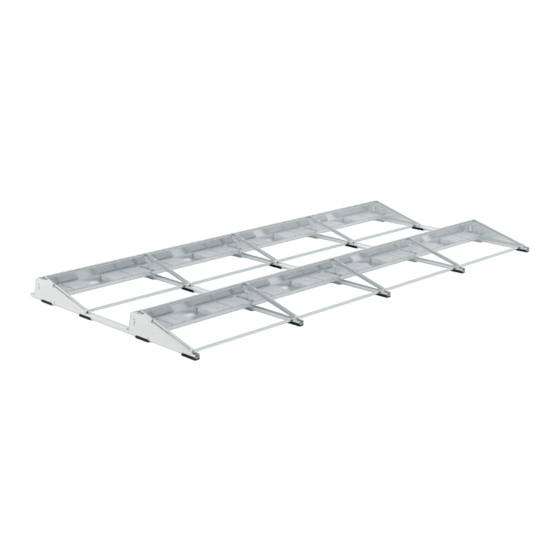
2. Basic information about the system FD3-S 10° FD3-S 15° Modulsize Modulsize Max. width: 1134mm Max. width: 1134mm Max. length: 2300mm Max. length: 2300mm Distance between the rows: 370mm Distance between the rows: 710mm FD3-South 2x4 15° FD3-S Premium Line... -
Page 6: Elements And Components
2.1 Elements and components Base rail 10° 1408mm (600-0372) 15° 1265mm (600-0376) Locking front support 250mm (600-0365) Connecting rail 1025mm (600-0370) Connecting rail 1475mm (600-0374) Connecting rail 1293mm (600-0375) Connecting profil south 585mm (600-0371) Ball locking pin Front support (814-0703) Rear support (711-0260) 6x50... - Page 7 Side reflector 10° right (801-0370) Side reflector 10° left (801-0396) Side reflector 15° right (801-0372) Side reflector 15° left (801-0371) Back Windreflector 1861mm (801-0376) Back Windreflector 2066mm (801-0377) Rail cover south 10° 370mm (600-0373) Back Windreflector 2200mm (801-0378) Rail cover south 15° 885mm (600-0377) Back Windreflector 2384mm (801-0385)
-
Page 8: Assembly
3. Assembly 3.1 Universal central and end support – 10° & 15° Fold the feet down and secure with two ball locking pins to desired positions 10° or 15°. See designation. 15° 10° CLICK CLICK Installation manual... -
Page 9: Front Support
3.2 Front support Install the front support in the cutouts at the side edge of the base rail Assembling the protection mat Lock together with the rail Pprotection mat beneath the up to an audible click front and middle support CLICK At the beginning of the system lock with component (2) -
Page 10: Rear Support
3.3. Rear support Place the rear support in the cutouts Place the front support in the cutouts. See page 20. Front support rotated 180° for back wind deflector for 15° 10° Lock the rear support with the connecting rail up to an audible click assamble protection mat CLICK... -
Page 11: Connecting Rails
3.4 Connecting rails Slide in CLICK up to an audible click assamble protection mat Connecting rail FD3-S Premium Line... -
Page 12: End Of The Rail Connection
3.5 End of the rail connection Lock together with the locking rear support assamble protection mat At the end of the system lock with component (4) Overview of the rails in a row 2 - 1 - 3 - 1 - 4 for further rows always put (3) and (1) in a row Installation manual... -
Page 13: Rail Layout
3.6 Rail layout Place the rails parallel to the length of the module. Distance gauge Rail spacing = Module length FD3-S Premium Line... - Page 14 3.7.1 Ballast tray for multi-row arrangement tray Note the maximum weight The number, position and weight of the per ballast tray necessary ballast (stones or gravel) should always be included in the project information Order First, place a narrow side on the outside Hole marked the wide side Insert the ballast tray...
- Page 15 Press the flap down For the first and last ballast tray (8), press the flap to be locked in the rail. Place further ballast trays on and press down only one flap. Apply ballast evenly, from the outside to the inside Note the maximum weight Ballast must be put in the ballast tray starting per ballast tray...
-
Page 16: Ballast Tray
3.7.2 Ballast tray for single row arrangement Note the maximum weight The number, position and weight of the per ballast tray necessary ballast (stones or gravel) should always be included in the project information Order First, place a narrow side on the outside Hole marked the wide side. - Page 17 Press the flap down For the first and last ballast tray (8), press the flap to be locked in the rail. Place further ballast trays on and press down only one flap. Apply ballast evenly, from the outside to the inside Note the maximum weight Ballast must be put in the ballast tray starting per ballast tray...
-
Page 18: Adapter Wind Deflector
3.8 Adapter wind deflector Mount on the middle support. Tighten with a torque of 8Nm. For the 10° variant, the adapter (9) must be rotated by 180°. South 15° South 10° 180° South 15° South 10° Installation manual... -
Page 19: Assembly Of Modules And Side Covers
3.9 Assembly of modules and side covers Arrange modules Insert in and fix the right (10) and left (11) side deflector Make sure the noses of the side deflector have been placed in the correct position, to ensure a correct grip. 10°... -
Page 20: End Clamp
3.10 End clamp Make sure that the bottom of the end clamp (17) is against the side deflector. End clamp 30-50mm Installation manual... -
Page 21: Middle Clamp
3.11 Middle clamp Torque wrench Allen key torque ratchet wrench Insert module clamps (18) Tighten Tighten with a torque of 8 Nm. FD3-S Premium Line... -
Page 22: Wind Deflector
3.12 Wind deflector Hang the wind deflectors (12) in the provided openings and fix them with screws. Sheet metal screw 6 Nm Cylinder head screw M6x16 6 Nm Installation manual... -
Page 23: Top Rail Cover
3.13 Top rail cover To be put only on the top cover after the cables have been passed through! Lock rail cover FD3-S Premium Line... - Page 24 D-15834 Rangsdorf D-51105 Köln www.mounting-systems.com www.mounting-systems.com Tel: +49 3370 8529 - 100 Tel: +49 221-29277 - 600 Fax: +49 3370 8529 - 199 Fax: +49 221-29277 - 629 Mail: info-de@mounting-systems.com Mail: info-de@mounting-systems.com Subject to technical alterations 2023 © Mounting Systems GmbH...
Need help?
Do you have a question about the Premium Series and is the answer not in the manual?
Questions and answers