Advertisement
Quick Links
PD100 Display
Quick Start Guide
Product Features
PSL Version
1
Ambient Light Sensor - Automatic screen brightness
control
2
Time of Flight Sensor - Reserved for Close Object
detection
3
Buzzer
4
Status indicator LED Strips - Refer to the LED Status
Indicator section for more details (PRM Version only)
Mounting
PD100 allows different mounting options:
Wall Mount
1.
Electrical Junction Box Mount
2.
Glass Mount
3.
PRM Version
Double Sided Tape
Glass
Cover Sheet
(Back of Glass)
Please visit
http://brtsys.com/warranty
for warranty registration with the UUID and Product Key
below:
STICKER AREA
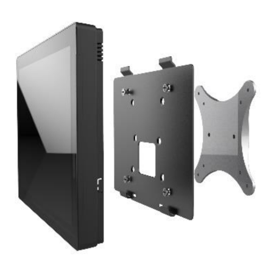
Mounting
VESA Mount
4.
Use the RJ45-JST8 cable (in the product package) to connect
➢
the PD100 display to the PanL Hub port. The Cable can reach
a maximum length of 100 meters if needed. The cable has an
RJ45 plug. Therefore, note that an RJ45 socket to RJ45 socket
adapter needs to be used if the extension cable is a plug-to-
plug type such as an Ethernet patch cable.
A PanL Hub port can only be connected to one PD100 display
➢
at a time; Daisy chaining is not applicable.
An RS485 terminator is built into the PD100 display and
➢
enabled.
ID switch on the back of the displays can be configured for
➢
unique settings or left as factory default. Factory default is 0.
Use a Philips head screwdriver to set a unique number
➢
between 0-7 (8- 9 are reserved).
or scan the QR code
Display Installation
ID Switch Configuration
Advertisement

Summary of Contents for BRT Systems PANL PD100
- Page 1 Please visit http://brtsys.com/warranty or scan the QR code for warranty registration with the UUID and Product Key PD100 Display below: Quick Start Guide STICKER AREA Product Features Mounting VESA Mount PSL Version PRM Version Ambient Light Sensor - Automatic screen brightness Display Installation control Time of Flight Sensor - Reserved for Close Object...
- Page 2 PD100 Display Quick Start Guide Device Start up Animation/Image After Power Up PD100 will display the following startup animation/image after connecting to the PanL Hub and powering ON. The LEDs on the PRM version will blink. PSL Version PRM Version LED Status Indicator The LED indicator at the side of the PD100 Display shows different display status as detailed in the table below - Status...
- Page 3 PD100 Display Quick Start Guide FCC Statement This equipment has been tested and found to comply with the limits for a Class B digital device, pursuant to part 15 of the FCC Rules. These limits are designed to provide reasonable protection against harmful interference in a building installation. This equipment generates, uses and can radiate radio frequency energy and, if not installed and used in accordance with the instructions, may cause harmful interference to radio communications.
Need help?
Do you have a question about the PANL PD100 and is the answer not in the manual?
Questions and answers