Table of Contents
Advertisement
Quick Links
Advertisement
Table of Contents

Related Manuals for AquaLabo LowTuS

Summary of Contents for AquaLabo LowTuS
- Page 1 LowTuS User manual V1.2 _ April2023...
-
Page 2: Table Of Contents
3.4 Packaging OVERVIEW OF THE LowTuS SENSOR 4.1 LowTuS versions description 4.2 Package contents 4.3 General view of the LowTuS sensor 4.3 Measurement chain description and measuring principle. 4.4 Available parameters 4.5 On site installation: Wall mounting configuration CONDITIONS OF USE 5.1 Fluidic circuit description... - Page 3 LowTuS Fluid temperature parameter Turbidity parameter - 3 -...
-
Page 4: Warranty
AQUALABO. For devices with a warranty form, it only applies if the form received with the device is returned to AQUALABO duly completed. SOFTWARE WARRANTY The software is guaranteed by the software publisher or distributor under the conditions specified in the documentation related to those software packages. -
Page 5: Information
If the equipment is not used immediately, it should be stored in a clean, dry place. Abide by the following storage temperatures (10-35°C). AQUALABO equipment is carefully inspected before packaging. Upon receipt of your device, check the condition of the packaging and if you notice an anomaly, submit the usual reservations with the carrier within 48 hours. Then consult the packing list and check that everything is in order. -
Page 6: Safety
Trained personnel should be familiar with and follow the instructions in this manual. 3.3 Notes on handling LowTuS turbidimeters are opto-electronic devices. As such, they must be treated with care. Always protect the device from conditions that could adversely affect its components. In particular, adhere to the following points: ➢... -
Page 7: Packaging
3.4 Packaging The LowTuS turbidimeter is shipped in packaging designed to protect it during transport. It is essential that you keep the original packaging as well as the inner packing in such a way as to ensure optimum protection of the device from impact in the event of transport. -
Page 8: Overview Of The Lowtus Sensor
Upon receipt of your device, check the condition of the packaging and if you notice an anomaly, submit the usual reservations with the carrier within 48 hours. If you notice that something is missing or the equipment is damaged, contact AQUALABO without delay. -
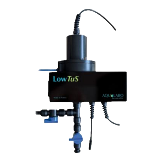
Page 9: General View Of The Lowtus Sensor
The PREMIUM version is described below with its automatic cleaning system built into the removable lid. In this version, a specific cable transfers energy from the main part of the LowTuS device to a motor in the lid to generate a cleaning process using a rotating arm with a rubber blade. - Page 10 The turbidity equivalent value of the tool is factory defined for the LowTuS device. Consequently, the tool is compatible with a single device. This tool contains two holes which combined with the pin fixed in the upper part of the measuring cell allow for two positions of use.
-
Page 11: Measurement Chain Description And Measuring Principle
The measurement principle is based on measuring InfraRed light diffusion at 90° (ISO 7027) and enables continuous monitoring of turbidity across low measurement ranges. The LowTuS device is an open protocol RS485 Modbus slave. It delivers temperature and turbidity values to a master. This master could be either a local display-controller-transmitter or a remote monitoring system. -
Page 12: Available Parameters
LowTuS 4.4 Available parameters LowTuS device is a digital sensor delivering the following data: Parameter Unit Description Temperature ° Celsius Fluid temperature: measurement located in the flow cell body. Two available ranges (see data sheet for details); Factory calibrated with diluted Turbidity Formazine standard solutions;... - Page 13 LowTuS - 13 -...
-
Page 14: Conditions Of Use
5. CONDITIONS OF USE 5.1 Fluid circuit description 5.1.1 Fluid configuration: The LowTuS device is compatible with analysing aqueous solutions. Organic solvents could damage plastic parts. Flow rates min / max: 100 ml/min – 1500 ml/min 5.1.2 Compatible pipe types: Fluid inlet and drain: - semi-rigid in PE Ø... -
Page 15: Fluidic Circuit Assembly
LowTuS 5.2 Fluid circuit assembly LowTuS is delivered with the valves unplugged. Please only connect the two pre-configured valves, INLET and DRAIN once the device has been wall-mounted. 5.2.1 Description of the pre-assembled valves: INLET valve: fluted tip inserted in one side of the valve; 50mm semi-rigid 10x12 PE tube in the other side, DRAIN valve: stopper inserted in one side of the valve;... -
Page 16: Inlet Or Outlet Tubes
LowTuS 5.3 INLET or OUTLET tubes 5.3.1 Tube quality control: Make sure that the tube used is clean and does not present any scratches, cracks or deformity. To avoid leakage, ensure that the tube size and the push-in system size of the fittings are the same. Cut the semi-rigid tube with the dedicated cutter tool to obtain a 90°... -
Page 17: Connection And Wiring
LowTuS 6. CONNECTION AND WIRING The LowTuS turbidimeter comes with a factory-installed cable (of a given length) with bare wires. CAUTION: Any modification of the connector installed by the manufacturer, bare wires or 6-contact plug, represents a major transformation of the product and entails a loss of guarantee. -
Page 18: Communication
These addresses can be modified by an operator wishing to manage a network of several sensors, thereby avoiding any conflict. 7.2 Device activity An RGB LED is in the front panel of the LowTuS sensor. It gives information to the user about device activity. LED color... -
Page 19: Maintenance/Cleaning Sequence
8. MAINTENANCE/CLEANING SEQUENCE 8.1 Maintenance steps - Stop the wiper cleaning cycle (turn off the LowTuS device). - Stop the fluid supply to the cell. If the drain valve is not connected to a drain pipe, put a tank under the flow cell. - Page 20 LowTuS After internal cleaning or calibration process, check the O-ring is in good condition, Close the flow cell, place the lid on the top of the flow cell. The right position is obtained when the pin is in the small hole.
-
Page 21: Calsens Software
The user can go directly from this window to: - SENSOR DETAILS, (magnifier icon) - CALIBRATION, - REAL TIME measurement. NOTE: The LowTuS device description contains “WIPER” if it is a premium version with an autocleaning system. - 21 -... - Page 22 LowTuS SENSOR DETAIL This window contains 4 main aspects: Description and versions, Network address selection, User settings button, Manual measurement window with description parameters, units, instantaneous values, measurement status. It enables occasional measurement of all available parameters during the device set-up phase.
- Page 23 Furthermore, the user can, in maintenance sequence, freeze the cleaning periodicity, or manually generate one cleaning action. During the life of the LowTuS device (premium version), the cleaning system’s rubber blade must be changed. Simultaneously, the user must reset the cleaning counter.
-
Page 24: Calibration
LowTuS The operator can select parameters between the available list and load this selection in a named CSV file. 9.3 Calibration 9.3.1 General The calibration screen can be accessed from the main screen when one or more sensors are selected. Only selected sensors will be calibrated. -
Page 25: Parameter Selection
LowTuS 9.3.2 Parameter selection application automatically selects the common parameters from all the sensors. Multiple calibration can only calibrate one parameter at a time. The operator's name has to be filled in before running the calibration. a. Fluid temperature parameter Two-step sequence i.e. - Page 26 LowTuS Step 1: Offset Subject the unit to water circulation in stabilized low temperature conditions, fluid at T1. master sends requests repeated measurements until sufficiently stable measurement is obtained, Write the temperature value T1 (°C), delivered by the reference equipment, in the "Reference value"...
- Page 27 LowTuS b. Turbidity parameter Complete calibration is performed with a static solution of formazine. 1. Close the taps to isolate the cell from the fluid circuit 2. Open the lid and pour 80ml to 100ml of clear water or formazine solution into the cell.
- Page 28 LowTuS Step 1: Offset Subject the unit to demineralized water. When the measurement is stabilized, write the turbidty value in the “reference value” box Step 2: Gradient Wipe the measuring cell with a clean cloth before adding a formazin solution.
Need help?
Do you have a question about the LowTuS and is the answer not in the manual?
Questions and answers