
Related Manuals for Funk Tonstudiotechnik SAM-3B.V2-EX


Summary of Contents for Funk Tonstudiotechnik SAM-3B.V2-EX
- Page 1 OPERATING MANUAL MULTI - BALANCING / DIFFERENTIAL / SUMMING - AND DISTRIBUTION AMPLIFIER SYSTEM...
-
Page 2: Table Of Contents
BALANCING AMPLIFIER SAM - 3B.V2-EX ________________________________________________________________________________ TABLE OF CONTENTS FOR YOUR SPECIAL ATTENTION Page DESCRIPTION Page 4..6 OPERATING INSTRUCTIONS Page INPUT/OUTPUT AMPLIFIER Page 8..10 STANDARD CONFIGURATION EXAMPLES Page 11..14 DISTRIBUTOR CONFIGURATION EXAMPLES Page 15..22 HUM LOOPS Page BLOCK DIAGRAM Page CONNECTOR ASSIGNMENT Page SUB-D ADAPTER 25/37-PIN... -
Page 3: For Your Special Attention
FOR YOUR SPECIAL ATTENTION _______________________________________________________________________________________________ These operating instructions are generally valid for all versions of the SAM-3B.V2-EX as long as no differences are pointed out. ATTENTION : Mains connection only permitted to AC voltage of 90..265 volts/45...400 Hz ! To avoid fire and electric shock, do not expose the unit to rain or moisture! If any liquid... - Page 4 INTRODUCTION...SAM-3B.V2-EX _______________________________________________________________________________________________________________________________ 4...16-CHANNEL MATCHING AMPLIFIER INTENDED USE : The SAM-3B.V2 EX is a professional MULTIANNAL UNIVERSAL SYMMETRIER/DIFFERENCE AMPLIFIER with excellent sonic characteristics for balancing/asymmetrising/distributing and summing, as well as for its high bandwidth for level and impedance matching for analogue audio or time code signals.
- Page 5 The balanced input stages are designed as particularly low-noise instrumentation amplifiers with high input impedance. This makes the SAM-3B.V2-EX one of the lowest noise units of its kind. At the same time, the signal source is hardly burdened by this circuitry measure.
- Page 6 INTRODUCTION SAM-3B.V2-EX ___________________________________________________________________________________________________________________________________ Configurations : The SAM-3B.V2 EX is modularly constructed with the 4-channel amplifier cards SIA-4.EX (balanced inputs to asym. outputs) and SOA-4EX (asym. inputs to asym. outputs) and can therefore be offered in different versions. Due to the service-friendly design, the amplifier modules incl. all sockets can be exchanged, extended or retrofitted in a few minutes without soldering.
-
Page 7: Operating Instructions
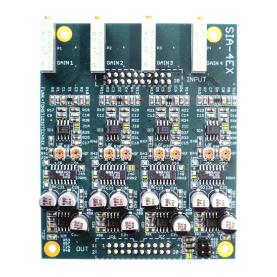
SAM-3B.V2-EX OPERATING INSTRUCTIONS _______________________________________________________________________________ Zum Einstellen der Verstärkung der Ein/Ausgangsverstärker durch die Rückwandbohrungen nur Schlitzschraubendreher mit 2...2,5 mm Klingenbreite und mindestens 30 mm Klingenlänge bzw. Kreuzschlitzschraubendreher Größe 0 verwenden! Rechtsdrehung der Spindeltrimmer vergrößert die Verstärkung. To adjust the gain of the input/output amplifiers through the rear panel holes, use only slotted screwdrivers with a blade width of 2...2.5 mm and a blade length of at least 30 mm or Phillips... - Page 8 SAM-3B.V2-EX INPUT AMPLIFIER (SIA-4EX) _______________________________________________________________________________ The SIA-4EX serves as a 4-fold differential amplifier (instrumentation amplifier) in the unit. Adjustment of the output levels is possible via the 19mm spindle trimmers P1a, P1b, P1c, P1d. The input symmetry at 1 kHz is adjusted via the trimmers P2a, P2b, P2c, P2d, the symmetry for high frequencies (10 kHz) is adjusted via P3a, P3b, P3c, P3d.
- Page 9 SAM-3B.V2-EX INPUT AMPLIFIER (SIA-4EX) _______________________________________________________________________________ The functions of the SIA-4EX amplifiers are set by various solder jumpers on the circuit board. The following diagram illustrates how these jumpers work. umpers J1A..J1D are normally open. The gain of the input stage is then exactly 1 (0.0 dB). Closing these jumpers increases the gain of the corresponding input stage by 6.0 dB.
- Page 10 SAM-3B.V2-EX OUTPUT AMPLIFIER (SOA-4EX) _______________________________________________________________________________ The SOA-4EX serves as a 4-fold balancing amplifier in the SAM-3B.V2 EX. Adjustment of the output levels is possible via the 19 mm spindle trimmers P1..P4. The output voltage and impedance symmetry is adjusted via SMD trimmers. These trimmers should...
-
Page 11: Standard Configuration Examples
STANDARD - CONFIGURATION EXAMPLES _________________________________________________________________________________________________________ STANDARD CONFIGURATIONS : The following diagram shows the schematic structure of an 8-channel balancing amplifier Balancing amplifier SAM-3B.V2-EX/8-0 Symmetrierverstärker SAM-3A/8-0 SYMMETRISCHE VERSTÄRKUNG AUSGANGSSTUFE VARIABEL 0...+20 dB I N 8 OUT 8 I N 7 OUT 7... - Page 12 ______________________________________________________________________________ STANDARD CONFIGURATIONS : The following diagram shows the schematic structure of a 16-channel balancing amplifier and the corresponding pin assignment of the 37-pin Sub-D connectors on the SAM-3B.V2-EX : Balancing amplifier SAM-3B.V2-EX/16-0 Symmetrierverstärker SAM-3A/16-0 VERSTÄRKUNG SYMMETRISCHE VARIABEL 0...+20 dB...
- Page 13 STANDARD - CONFIGURATION EXAMPLES ______________________________________________________________________________ STANDARD CONFIGURATIONS : The following diagram shows the schematic structure of a 16-channel differential amplifier and the corresponding pin assignment of the 37-pin sub-D connectors on the SAM-3B.V2-EX : Differential amplifier SAM-3B.V2-EX/0-16 Differenzverstärker SAM-3A/0-16 SYMMETRISCHE BUFFERSTUFE EINGANGSSTUFE...
- Page 14 The following diagram shows the schematic structure of an 8-channel balancing amplifier and an 8-channel differential amplifier and the corresponding pin assignment of the 37-pin sub-D connectors on the SAM-3B.V2-EX : Balancing and differential amplifier SAM-3B.V2-EX/8-8 Symmetrier- und Differenzverstärker SAM-3A/8-8 VERSTÄRKUNG SYMMETRISCHE VARIABEL 0...+20 dB...
- Page 15 SPECIAL VERSIONS (fully balanced distribution amp.) SAM-3B.V2-EX ______________________________________________________________________________ SPECIAL CONFIGURATIONS : The current versions of the SAM-3B.V2 EX can also be equipped with more than 16 amplifier channels. This can be useful for distribution amplifiers that are to be fully balanced. The following are some examples of such configurations.
- Page 16 SPECIAL VERSIONS (full- balanced distribution amp.) SAM-3B.V2-EX ______________________________________________________________________________ SPECIAL CONFIGURATIONS : The following example shows the construction of a distribution amplifier 4x 1 on 2 with 8 balanced output stages and 4 balanced input amplifiers with the corresponding wiring of the Sub-D connectors.
- Page 17 SPECIAL VERSIONS (fully balanced distribution amp.) SAM-3B.V2-EX ______________________________________________________________________________ SPECIAL CONFIGURATIONS : The following example shows the design of a distribution amplifier 1x 1 to 16 with 16 symmetrical output stages and 1 symmetrical input amplifier with the corresponding wiring of the Sub-D connectors.
- Page 18 SPECIAL VERSIONS (fully balanced distribution amp.) SAM-3B.V2-EX ______________________________________________________________________________ SPECIAL CONFIGURATIONS : The following example shows the construction of a distribution amplifier 2x 1 to 6 with 12 symmetrical output stages and 2 symmetrical input amplifiers with the corresponding wiring of the Sub-D connectors.
- Page 19 SPECIAL VERSIONS (fully balanced distribution amp.) SAM-3B.V2-EX ______________________________________________________________________________ SPECIAL CONFIGURATIONS : The following example shows the construction of a distribution amplifier 2x 1 on 8 with 16 balanced output stages and 2 balanced input amplifiers with the corresponding wiring of the Sub-D connectors.
- Page 20 SPECIAL VERSIONS (fully balanced distribution amp.) SAM-3B.V2-EX ______________________________________________________________________________ SPECIAL CONFIGURATIONS : The following example shows the construction of a distribution amplifier 4x 1 on 4 with 16 balanced output stages and 4 balanced input amplifiers with the corresponding wiring of the Sub-D connectors.
- Page 21 SPECIAL VERSIONS (fully balanced distribution amp.) SAM-3B.V2-EX ______________________________________________________________________________ SPECIAL CONFIGURATIONS : The following example shows the construction of a summing amplifier 4x 4 on 1 with 16 symmetrical input stages and 4 symmetrical output amplifiers with the corresponding wiring of the Sub-D connectors.
- Page 22 SPECIAL VERSIONS (fully balanced distribution amp.) SAM-3B.V2-EX ______________________________________________________________________________ SPECIAL CONFIGURATIONS : The following example shows a fully balanced 4-channel level and impedance matching amplifier 1 on 1 with 4 balanced inputs and 4 balanced outputs with the corresponding wiring of the Sub- D connectors.
-
Page 23: Hum Loops
The following diagram shows the effect of a ground loop separation within an asymmetrical cabling by interposing a balanced amplifier input (differential amplifier SAM-3B.V EX). High impedance "instrumentation amplifiers" such as those used in the SAM-3B.V2-EX ideally only take into account the voltage difference between their two inputs. If the two inputs are connected to each other and then modulated together, no signal is produced at the output. -
Page 24: Block Diagram
_______________________________________________________________________________ SIMPLIFIED BLOCK DIAGRAM The following block diagrams of the audio amplifiers used in the SAM-3B.V2-EX show only 1 channel of the corresponding 4-channel amplifier. The highly simplified diagrams only serve for a basic understanding of the mode of operation of the SIA-4EX and SOA-4EX modules. -
Page 25: Connector Assignment
SAM – 3B.V2-EX INPUT AND OUTPUT ASSIGNMENT ______________________________________________________________________________ Pin assignment audio signals The inputs and outputs for channels 9..16 are connected identically. For the wiring, 37-pin sub-D connectors female are required for the inputs and outputs. - Page 26 Adapters from the common 25-pin configuration to the 37-pin connection used in the unit are optionally available. This allows the use of inexpensive 25-pole SUB-D cables on the SAM-3B.V2-EX. At the same time, the adapter for the inputs on the 25-pin side converts the signal to a female connector.
- Page 27 SAM – 3B.V2-EX SUB-D-ADAPTER 25-Pol/37-Pol _____________________________________________________________________________...
-
Page 28: Technical Data
Technical data SAM-3B.V2-EX ________________________________________________________________________________ SOA-4EX Modul asym. inputs ⇒ sym. outputs (Input signal 1 kHz +6 dBu with gain 0 dB, R = 10 kΩ) Gain : ............0 dB...+ 23 dB adjustable by spindle trimmer set to + 10 dB on delivery (0.0 dB for distribution amplifiers) Input resistance : .......... -
Page 29: Interference Radiation And Immunity
FOR YOUR SPECIAL ATTENTION _____________________________________________________________________________ INTERFERENCE RADIATION AND INTERFERENCE IMMUNITY The unit complies with the protection requirements in the field of electromagnetic compatibility, which are listed in Directives 89/336/EEC and FCC, Part 15, among others : The electromagnetic emissions generated by the unit are limited to such an extent that proper operation of other devices and systems is possible. -
Page 30: Maintenance And Repair
MAINTENANCE AND REPAIR _____________________________________________________________________________ SAFETY Interventions in the unit may only be carried out by qualified personnel in compliance with the applicable regulations. Before removing housing parts, the unit must be switched off and disconnected from the mains. When carrying out maintenance work on the open, mains-operated unit, bare circuit parts and metal semiconductor housings must not be touched either directly or with an uninsulated tool. -
Page 31: Ce Declaration Of Conformity
Protection class 1, EN60950; 1992 + A1/A2; 1993 EMV : EN55103-1 EN55103-2 Evaluation criterion B electromagnetic environment E4 Berlin, 5.09.2022 Th. Funk, Owner FUNK TONSTUDIOTECHNIK GERMANY 10318 BERLIN BLOCKDAMMWEG 39-59 0049 (0)30 6115123 : (0)30 6123449 Information: www.funk-tonstudiotechnik.de E-MAIL: funk@funk-tonstudiotechnik.de...
Need help?
Do you have a question about the SAM-3B.V2-EX and is the answer not in the manual?
Questions and answers