Table of Contents
Advertisement
Quick Links
Operation Manual
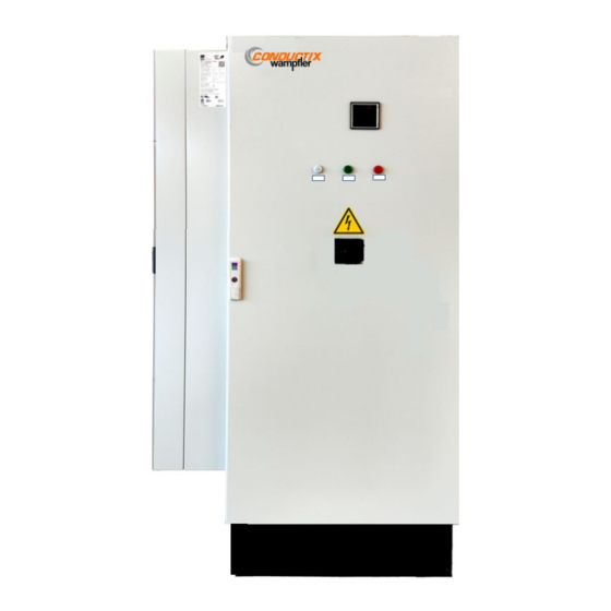
Track Supply i40 kW
80 / 125 A at 400 / 480 V
Order Numbers Air-Conditioned Units / RAL7035
91008-111-3298726 ( 80 A, 400 V, RAL 7035 – light grey, Air Condition)
91012-111-3297751 (125 A, 400 V, RAL 7035 – light grey, Air Condition)
91008-111-3298727 ( 80 A, 480 V, RAL 7035 – light grey, Air Condition)
91012-111-3297752 (125 A, 480 V, RAL 7035 – light grey, Air Condition)
Shown 91012-111-3297751
Air conditioned
BAL9100-0149-EN
www.conductix.com
Order Numbers Forced Air Cooled Units / RAL7035
91008-111-3298724 ( 80 A, 400 V, RAL 7035 – light grey, Forced Air Cooling)
91012-111-3297749 (125 A, 400 V, RAL 7035 – light grey, Forced Air Cooling)
91008-111-3298725 ( 80 A, 480 V, RAL 7035 – light grey, Forced Air Cooling)
91012-111-3297431 (125 A, 480 V, RAL 7035 – light grey, Forced Air Cooling)
original document
Shown 91012-111-3297749
Forced Air Cooling
page 1 of 52
Advertisement
Table of Contents

Summary of Contents for Conductix-Wampfler RAL7035
- Page 1 80 / 125 A at 400 / 480 V Order Numbers Air-Conditioned Units / RAL7035 Order Numbers Forced Air Cooled Units / RAL7035 91008-111-3298726 ( 80 A, 400 V, RAL 7035 – light grey, Air Condition) 91008-111-3298724 ( 80 A, 400 V, RAL 7035 – light grey, Forced Air Cooling) 91012-111-3297751 (125 A, 400 V, RAL 7035 –...
-
Page 2: Table Of Contents
Operation Manual Track Supply i40 kW 80 / 125 A at 400 / 480 V Contents Understanding ................................... 5 Limitation of Liability ............................... 5 Copyright ..................................5 Replacement parts ................................. 6 Material defects ................................6 Technical support ................................6 Symbols and Hints ..................................7 Advisory Information for the User ............................ - Page 3 Operation Manual Track Supply i40 kW 80 / 125 A at 400 / 480 V General Features ................................18 Safety Features of Track Supply ..........................19 Grounding ..................................19 Configuration Options ................................20 Configuration with Air Conditioning Unit (mounted on the Side) .................. 20 Configuration Operating Frequency ..........................
- Page 4 System related details please find in the system manuals. Refer always to the system documentation before starting any work on the system or components within the system or before operating the system. Reprint and duplication (as well as extracts) are only allowed with permission from Conductix-Wampfler GmbH. Conductix-Wampfler GmbH 2023 BAL9100-0149-EN www.conductix.com...
-
Page 5: Understanding
Provision of the operating instructions to third parties, reproductions in any form – even in part – as well as the reuse and/or disclosure of their content are not permitted without the written approval of the Conductix-Wampfler, except for the customer's internal use. -
Page 6: Replacement Parts
WARNING! → Only use original Conductix-Wampfler replacement parts! Replacement parts can be ordered an authorized dealer or directly from Conductix-Wampfler. 1.4 Material defects The terms governing material defects can be found in the General Terms and Conditions of business. -
Page 7: Symbols And Hints
Operation Manual Track Supply i40 kW 80 / 125 A at 400 / 480 V 2 Symbols and Hints Warning of voltage This symbol can be found in several places in the operating instructions where special care has to be taken due to a voltage presence which is hazardous to people. -
Page 8: Advisory Information For The User
Conductix-Wampfler GmbH cannot be responsible for damage or breakdowns that have been caused by not observing the instruction manual. These operating instructions contain exclusively details of the Track Supply component. -
Page 9: Brief Technical Description
Operation Manual Track Supply i40 kW 80 / 125 A at 400 / 480 V 4 Brief Technical Description The Track Supply serves to supply energy to the secondary components in system in a defined segment of a i.e., material handling system. The Track Supply converts the 400 50 Hz or 480 V 60 Hz mains voltage, depending on type, to a constant 20 kHz sinusoidal current. - Page 10 Operation Manual Track Supply i40 kW 80 / 125 A at 400 / 480 V Regarding the installation place and distances pay attention to the chapter 7.1 “Configuration with Air Conditioning Unit (mounted on the Side)”! Figure 2: Components inside (photo shows optional C-Box (to order separately)) Air out Air in Power Module...
-
Page 11: Type With Forced Air Cooling
Operation Manual Track Supply i40 kW 80 / 125 A at 400 / 480 V 5.2 Type with Forced Air Cooling Figure 3: Appearance and main components of Track Supply with Forced Air Cooling Display-Window Status-LED’s Main switch Door lock BAL9100-0149-EN www.conductix.com original document... - Page 12 Note that the picture above may not in some cases correspond exactly to the delivered component (for example color or wiring positions). If you have concerns, you have not been delivered the correct item please contact a Conductix-Wampfler representative. BAL9100-0149-EN www.conductix.com...
-
Page 13: Technical Data
Operation Manual Track Supply i40 kW 80 / 125 A at 400 / 480 V 6 Technical Data 6.1 Electrical Data - Specifications 6.1.1 Electrical Output Data – Specifications for 400V and 480V Versions 40 kW Continuous output power Overload capability 50 kW for max. -
Page 14: Physical Data
Operation Manual Track Supply i40 kW 80 / 125 A at 400 / 480 V 6.2 Physical Data 6.2.1 Type without Air Conditioning During operation 57 dBA at 2 m distance in front Noise levels Air volume moved 500 m³ / hour (air recirculation) 1 axial fan 6.2.2 Type with Air Conditioning... - Page 15 Operation Manual Track Supply i40 kW 80 / 125 A at 400 / 480 V The Track Supply requires for the correct cooling a sufficient air flow. Figure 5: Air flow with Air Conditioning Figure 6: Air flow with Forced Air Cooling Recommended clearances: 400 mm over the Track Supply Minimum 1000 mm in front of the Track Supply to access the door...
-
Page 16: Mechanical Data
Operation Manual Track Supply i40 kW 80 / 125 A at 400 / 480 V 6.4 Mechanical Data Cabinet Rittal VX25 with right-hand hinged front door Locking Standard locking for Rittal cabinets Rittal VX25 Hinges 130° opening angle Dimensions see the following drawing Color cabinet (outside) RAL 7035 “lightgrey”... -
Page 17: Dimensions Of Units With Air Conditioning
Operation Manual Track Supply i40 kW 80 / 125 A at 400 / 480 V 6.4.2 Dimensions of units with air conditioning Figure 8: Dimensional drawing (air conditioning, side mounted) 6.5 Connectors Figure 9: connectors (bottom view) Track connection (X1), see chapter 6.5.1 Connection to AC mains supply (X2), see chapter 6.5.2 Control and synchronization (X3), see chapter 6.5.3 BAL9100-0149-EN... -
Page 18: Track Connection (X1)
Operation Manual Track Supply i40 kW 80 / 125 A at 400 / 480 V 6.5.1 Track connection (X1) Pin Function Remarks Track cable 1 Up to 35 mm² lug soldered HF Litz cable * Track cable 2 * = cable shoes with M8 hole! 6.5.2 Connection to AC mains supply (X2);... -
Page 19: Safety Features Of Track Supply
Operation Manual Track Supply i40 kW 80 / 125 A at 400 / 480 V 6.7 Safety Features of Track Supply In-built temperature sensors and switches Over temperature Output load monitoring Overload Internal current monitoring Over current Output voltage control Overvoltage on output Input to output isolation 2500 V AC for 1 min... -
Page 20: Configuration Options
Operation Manual Track Supply i40 kW 80 / 125 A at 400 / 480 V 7 Configuration Options 7.1 Configuration with Air Conditioning Unit (mounted on the Side) The Air Conditioning unit is located on the left side of the track supply. Pay attention to the recommended distances to the neighboring equipment or walls (min. -
Page 21: Configuration Operating Frequency
The operating frequency of the power supply module is set via two DIP switches in the power supply module. Warning! To avoid damaging and interrupting operations, only Conductix-Wampfler service employees may adjust settings. 7.2.1... -
Page 22: Dip-Switch Setting Examples
Operation Manual Track Supply i40 kW 80 / 125 A at 400 / 480 V 7.2.2 DIP-Switch Setting Examples System with 4 separately feed Segments – DIP-Switch Settings assure different frequencies at each transfer point. System with 3 separately feed Segments – DIP-Switch Settings assure different frequencies at each transfer point. System with 3 separately feed Segments –... -
Page 23: Control Board Hardware And Failure Indication
Operation Manual Track Supply i40 kW 80 / 125 A at 400 / 480 V 8 Control Board Hardware and Failure Indication 8.1 Track Supply Display For displaying operational and error messages and for manual operation, the power supply module has an operating panel (display and keypad). -
Page 24: Track Supply Display Message
Operation Manual Track Supply i40 kW 80 / 125 A at 400 / 480 V 8.2 Track Supply Display Message If the power supply module has a disorder, the error appears in the display of the power supply module. In the display, if there is an occurred error, the last line “State:”... -
Page 25: Track Supply Error Codes
Operation Manual Track Supply i40 kW 80 / 125 A at 400 / 480 V 8.4 Track Supply Error Codes Note that one and the same problem can lead to different error codes, depending on the time of occurrence. This is because the error detection methods and reaction times differ for each type of error and also due to the mainly sequential processing by the microprocessor. -
Page 26: Door Switch
Operation Manual Track Supply i40 kW 80 / 125 A at 400 / 480 V 9 Door Switch The function of the main door switch is to isolate the inverter stage of the Track Supply, thus disconnecting the output from power even when an Enable signal is applied. -
Page 27: Mains Fuses
Operation Manual Track Supply i40 kW 80 / 125 A at 400 / 480 V 10 Mains Fuses Used fuse see chapter 22. Attention: The Track Supply is without any voltage inside only when the plug or the power supply is disconnected for at least 20 minutes. -
Page 28: Transport And Storage
• The Track Supply may contain other small fuses and circuit-breakers but changing these without consulting Conductix-Wampfler is not recommended. In case of repair the Track Supply must be disconnected from the mains supply and adequate discharging time (at least 10 minutes to reduce voltages to < 60Vdc) must be observed. -
Page 29: Installation
• When operating several track supplies in one plant the control board may need to be synchronized. Conductix-Wampfler provides documentation with the synchronization components. For the installation of the Track Supply make sure that it is positioned safely and on an even surface. It has to be secured on site so that the position of the Track Supply will be permanently safe! The Track Supply center of gravity is offset relative to the middle of the base. -
Page 30: Place And Conditions Of Installation
Air Conditioning Unit (mounted on the Side)”. The ambient temperature should not be lower than 5°C and must not exceed the Conductix-Wampfler specification of 40°C. The relative air humidity should be below 90% and there must not be any condensation. -
Page 31: Electrical Connection
HARTING. These may be required for cables used in longer cable runs. • For supply voltages other than specified please consult Conductix-Wampfler. Attention! To avoid damaging the input fuses we recommend that the 3 phase mains supply shall be only removed when the START / STOP- signal is in the “STOP”... -
Page 32: Configuration Of Control Plug X3
Operation Manual Track Supply i40 kW 80 / 125 A at 400 / 480 V 12.5.2 Configuration of control plug X3 Figure 17: Excerpt from the circuit diagram (X3) Inputs Reset+ (Pin 3) must be taken 24 V DC above Reset - (Pin 4), otherwise the Track Supply remains in a reset /Reset state. -
Page 33: Connection Track Cable (X1)
Operation Manual Track Supply i40 kW 80 / 125 A at 400 / 480 V 12.5.3 Connection Track Cable (X1) 12.5.3.1 Routing of the Connection Track Cable (X1) Tightening torque for the X1.1 and X1.2 connection terminals of the track cables: 9-10 Nm Torque must be checked frequently. -
Page 34: Adding An Extra C-Box
Operation Manual Track Supply i40 kW 80 / 125 A at 400 / 480 V 12.5.3.2 Adding an extra C-Box (to order separately Run Litz Cables tied together closely through the Track Supply wherever possible! Use cable ties for tying. Don`t damage cable insulation while tying cables! Adding an extra C-Box in the Track Supply, should be considered on an exceptional basis only. -
Page 35: Arrangement External Connections (X1, X2, X3)
Operation Manual Track Supply i40 kW 80 / 125 A at 400 / 480 V 12.5.3.3 Arrangement external Connections (X1, X2, X3) Figure 19: connectors (bottom view) Track connection (X1) Connection to AC mains supply (X2) Control and synchronization (X3) NOTE: Pay attention to leaving cable ends long enough to make connections. -
Page 36: Wiring Of The Track Supply X2 And X3
Operation Manual Track Supply i40 kW 80 / 125 A at 400 / 480 V 12.5.4 Wiring of the Track Supply X2 and X3 Figure 20: connectors (bottom view) Track connection (X1) Connection to AC mains supply (X2) Control and synchronization (X3) Figure 21: Excerpt from the circuit diagram (X2) Figure 22: Excerpt from the circuit diagram (X3) BAL9100-0149-EN... -
Page 37: Warnings And Cautions
The Track Supply is only foreseen to be operated in conjunction with matching components by Conductix- Wampfler. If you are not sure whether components match, contact Conductix-Wampfler. Do not put into operation beforehand. -
Page 38: Commissioning
Prior to commissioning pay attention to warnings and hints in chapter 13 “Warnings and Cautions”. Track supplies have to be commissioned in conjunction with other corresponding Conductix-Wampfler components. For commissioning it is thus necessary to have the secondary components installed on the vehicles. -
Page 39: Start And Operation
15 Start and Operation! The Track Supply is not designed for independent operation. It has to be operated in conjunction with corresponding Conductix-Wampfler components. Therefore, no specific details about the operation are given in this document. Prior to switching-on the Track Supply ensure that the installation and commissioning were executed correctly. -
Page 40: Switching-Off
Operation Manual Track Supply i40 kW 80 / 125 A at 400 / 480 V 16 Switching-Off As described earlier (see chapter 12.5 “Electrical Connection”): first switch-off the Track Supply by switching the START-input to “OFF” and after this disconnect the line voltage (i. e. by a load switch). The system should be turned off using the load-break switch only in exceptional cases (see also Chapter 9 “Door Switch”). -
Page 41: Fault Diagnosis
Operation Manual Track Supply i40 kW 80 / 125 A at 400 / 480 V 18 Fault diagnosis If the Track Supply faults - e. g. no energy supply to the secondary components, check the LED display for indication of possible cause. Refer to chapter 8 “Control Board Hardware and Failure Indication” for LED status. -
Page 42: Maintenance
All the notes listed in this document must be strictly observed. It is moreover required to observe the general national prescriptions and specific factory regulations. Adjustments concerning inductivity may only be made by qualified personnel of Conductix-Wampfler. Qualified personnel, according to the safety regulations, are persons that are familiar with the installation, assembly, commissioning, and operation of energy supply systems and that have the appropriate qualifications. - Page 43 6 months. NOTE! For a qualified check of the operating parameters of the system, please contact Conductix-Wampfler. Thus, you can compare the currently measured values with those obtained during commissioning or the last inspection. Here you can also check free airflow inside the housing and specific torques.
-
Page 44: Repair
If repair action or replacement of faulty parts is necessary and possible on site these works have to be carried out only by trained personnel or by a Conductix-Wampfler technician, both while considering the relevant safety regulations. If no failure analysis or repair is possible on site the faulty part has to be sent to Conductix-Wampfler GmbH. -
Page 45: Disassembly/Re-Use
Operation Manual Track Supply i40 kW 80 / 125 A at 400 / 480 V 21 Disassembly/Re-use If it is necessary to exchange the Track Supply due to damage or to install it in another place, verify that no damage can occur during disassembly. For installation in another place observe the described mounting and commissioning instructions. -
Page 46: Spare Parts
80 / 125 A at 400 / 480 V 22 Spare parts Only the fuses and a few other parts are to be changed by the operator of the plant! All other parts have to be changed or repaired by trained and qualified Conductix-Wampfler personnel. Designation Producer... -
Page 47: Tools
Operation Manual Track Supply i40 kW 80 / 125 A at 400 / 480 V 23 Tools Description Size / Remarks specification Open ended or ring spanner diff. sizes Connection track cable wrenches, in case nuts (20 and 35 mm Litz cable) Hex Allen Key 4 mm... -
Page 48: Adjustments During The Commissioning And Start-Up
Operation Manual Track Supply i40 kW 80 / 125 A at 400 / 480 V 24 Adjustments during the commissioning and start-up Track Supply ____ A _____ V @ _____ Hz Material-No.: _______________________________ Serial number ..................Name of the project or line .................. -
Page 49: Inspection Report
Operation Manual Track Supply i40 kW 80 / 125 A at 400 / 480 V 25 Inspection Report Inspection report _____________________ Material-No.: _______________________________ Track Supply ____ A _____ V @ _____ Hz Serial number ..................Name of the project or line .................. - Page 50 Operation Manual Track Supply i40 kW 80 / 125 A at 400 / 480 V Inspection Report Inspection report _____________________ Track Supply ____ A _____ V @ _____ Hz Material-No.: _______________________________ Serial number ..................Name of the project or line ..................
- Page 51 Operation Manual Track Supply i40 kW 80 / 125 A at 400 / 480 V Inspection Report Inspection report _____________________ Track Supply ____ A _____ V @ _____ Hz Material-No.: _______________________________ Serial number ..................Name of the project or line ..................
- Page 52 Operation Manual Track Supply i40 kW 80 / 125 A at 400 / 480 V Conductix-Wampfler GmbH Phone: +49 (0) 7621 662-0 Rheinstraße 27 + 33 Fax: +49 (0) 7621 662-144 79576 Weil am Rhein - Märkt info.de@conductix.com Germany www.conductix.com Importer for the United Kingdom: Conductix-Wampfler Ltd.
Need help?
Do you have a question about the RAL7035 and is the answer not in the manual?
Questions and answers