
Summary of Contents for BLIIoT RTU5028E
- Page 1 Network Fault Monitoring Alarm RTU5028E User Manual Version:V1.1 Date:2020-01-07 Shenzhen Beilai Technology Co.,Ltd Website:https://www.bliiot.com...
- Page 2 RTU5028E Preface Thanks for choosing BLIIoT Network Fault Monitoring Alarm. These operating instructions contain all the information you need for operation of RTU5028E. Copyright This user manual is owned by Shenzhen Beilai Technology Co., Ltd. No one is authorized to copy, distribute or forward any part of this document without written approval of Shenzhen Beilai Technology.
-
Page 3: Table Of Contents
9.1 Modify Password ....................18 9.2 Time Zone ......................18 9.3 Set the SIM Card Number ...................19 9.4 Set RTU5028E System Time ................19 9.5 Inquiry Current Status ..................20 9.6 Set Daily Report Time ..................20 9.7 Set Interval Report Time ..................20 9.8 Set Authorized User number ................21... - Page 4 Network Fault Monitoring Alarm RTU5028E 9.10 Set Voltage High and Low Limits ..............21 9.11 Set Alarm Confirmation Time ................22 9.12 Set Alarm/Recovery SMS Content ..............22 9.13 Set Relay Output ....................23 9.14 Set PING Network Device IP ................23 9.15 Set PING External Network IP or Domain Name ..........
-
Page 5: Product Introduction
GSM/3G/4G network. RTU5028E power failure and network fault monitoring alarm is suitable for classrooms, public places, hospitals, stations, food warehouses, offices, factories, libraries, laboratories, etc., and any place that requires and supports power and network... -
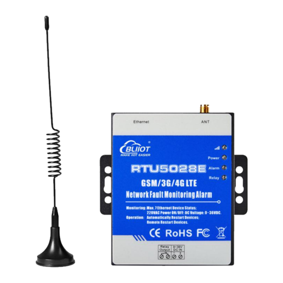
Page 6: Packing List
Network Fault Monitoring Alarm RTU5028E 3 Packing List 4 Features Network failure + power failure + network cable monitoring, remote monitoring the status of network device in many aspects; Support monitoring up to 7 network devices simultaneously; 1 relay output for automatic restart or remote restart of network equipment;... -
Page 7: Technical Specifications
Network Fault Monitoring Alarm RTU5028E Support remotely read 100 historic data via SMS or configuration software; Support Modbus RTU, Modbus TCP and MQTT protocol, can be connected to cloud platform; GSM/GPRS/3G/4G/Ethernet network communication, automatic connect to cellular network when wired network failed;... -
Page 8: Interface
Network Fault Monitoring Alarm RTU5028E LED Indicators When 2G module signal is normal, it flashes slowly (flash every 2 seconds), and flashes quickly when there is no signal (flash every 0.8 seconds); When the 3G/4G module signal is normal, the light turns off once... -
Page 9: Reset
Network Fault Monitoring Alarm RTU5028E installing the SIM card). 7 Reset 1) Power on the device, press and hold the reset button for 3 seconds, and wait for the power indicator to flash 3 times, indicating that the reset is successful. -
Page 10: Configuration Software
Network Fault Monitoring Alarm RTU5028E 8 Configuration Software When connecting to the configuration software for the first time, it is recommended to connect the device to a router with the DHCP automatic IP assignment function; if the network connected to the device cannot automatically assign IP, the device will use the following default network parameters after connecting to the network cable and waiting for 1 minute: IP address 192.168.1.111, subnet mask 255.255.255.0, and... -
Page 11: Selection
Network Fault Monitoring Alarm RTU5028E 8.2 Selection 【Device Password】Default 1234 【Connection】Configuration after a connection has been established 【Read】 Read the current configuration of the device, please read it before editing the parameters 【Save】Write the edited parameters into the device, and the edited parameters will take effect only after saving. - Page 12 Network Fault Monitoring Alarm RTU5028E digits, which is used for automatic time calibration of the device. If the network port cannot be connected to the Internet when it is turned on, the device will send a text message to itself to obtain the time of the SIM card operator.
-
Page 13: Number Settings
Network Fault Monitoring Alarm RTU5028E 8.4 Number Settings 【User Tel Number】Each number supports a maximum of 22 digits, please add country codes, such as "0086". 【Dial】If checked, this number will be dialed when the alarm occurs. 【SMS Report】If checked, the number can receive regular reporting SMS. -
Page 14: Alarm Settings
Network Fault Monitoring Alarm RTU5028E 8.5 Alarm Settings 【Channel Name】Name of each device. 【High Alarm SMS】【Low Alarm SMS】【Recover Content】【Alarm Content】The SMS content sent by the device. 【Threshold High】 【Threshold Low】 Once current voltage value higher/lower than threshold value, SMS content will be sent to authorized numbers. -
Page 15: Network Settings
Network Fault Monitoring Alarm RTU5028E for 2 seconds for the last time if it has not recovered after 5 minutes). 8.6 Network Settings 【LAN Settings】 【Obtain IP Address Automatically】The device will automatically obtain an IP address through DHCP. 【Fixed IP】When checked, the local connection settings can be customized. - Page 16 【Server Settings】 【Server 1 Domain/IP】【Server Port】The main server address, if the device uses the Modbus RTU protocol to connect to the BLIIoT Cloud Platform, the server address is modbusrtu.kpiiot.com:4000; if the device uses the Modbus TCP protocol to connect to the BLIIoT Cloud Platform, the server address is mbtcp.my-m2m. com:6655; if the device uses the MQTT protocol to connect to BLIIoT Cloud Platform, the server address is mqtt.my-m2m.com:1883...
-
Page 17: Alarm Record
Network Fault Monitoring Alarm RTU5028E 【Timer Report Interval Time】The range is 0~65535 seconds, default 60 seconds, which means that the device will upload data to the server every 60 seconds. 【Reconnection Settings】 【Reconnection Interval Time】The range is 0~65535 seconds, default is 600 seconds, which means that after the cellular network fails to connect to the server, it will try to connect again at an interval of 600 seconds. -
Page 18: Sms Command
Network Fault Monitoring Alarm RTU5028E 【Read Record】Read the last 100 historical records. 【Export Record】Export records to CSV format file. 9 SMS Command 1.Default Password is 1234. 2.The device doesn't support PIN Code Protected SIM Card. 3.You can program the device with SMS commands. -
Page 19: Set The Sim Card Number
Return SMS Example PWD+TEL+x+# 1234TEL008613570810254# x stand for the unit phone Set success! Stands for the unit phone number is number, max 22 digits 13570810254 9.4 Set RTU5028E System Time Command Return SMS Example PWD+D20xx-yy-zz+Thh:mm 1234D2018-01-02T03:0 or PWD+Dxxyyzz+Thhmm Notice: xx(Y)xx(M)xx(D)xx(H)xx... -
Page 20: Inquiry Current Status
Network Fault Monitoring Alarm RTU5028E 9.5 Inquiry Current Status Command Return SMS Current time; Device Name; External Power Normal/Failure/Voltage Higher: Current value; Device 1:Normal/Fault Device 2:Normal/Fault PWD+EE Device 3:Normal/Fault Note: Only set to Ping device IP Device 4:Normal/Fault Inquiry and internet IP, the return SMS will... -
Page 21: Set Authorized User Number
Network Fault Monitoring Alarm RTU5028E 999, stands for disable report) Inquiry PWD+DT 9.8 Set Authorized User number Command Return SMS PWD+A+x+T+y 1: --- (x= 01~10,must be 2 digits, stands for series number) 2: --- (y stands for phone number, max 22 digits, supports add country code, e.g. -
Page 22: Set Alarm Confirmation Time
Network Fault Monitoring Alarm RTU5028E PWD+AINR+x+L+y+H+z+# y stands for low threshold value; z stands for high threshold Voltage: value, if y=z, will not alarm. Voltage value should be setup at 10 Low: y, multiples of actual value. High: z. 1234AINRL50H250# To setup voltage low threshold as 5V, high threshold as 25V. -
Page 23: Set Relay Output
Network Fault Monitoring Alarm RTU5028E Inquiry PWD+AINA+x PWD+AINN+x+T+y Recover x=1~9; 1~7 stands for network device 1~7, 8 stands for Content: y Set Recover internet, 9 stands for external power, Content y stands for recovery alarm content, max 40 characters. 1234AINN9Tfault to set internet recover alarm... -
Page 24: Set Local Connection
Network Fault Monitoring Alarm RTU5028E 9.16 Set Local Connection The local connection is automatically obtained by DHCP. If you need to set a fixed IP, please set the relevant parameters according to the local area network. Command Return SMS PWD+ETHIP+x+*+y... -
Page 25: Set Cellular Network Access Parameters
Network Fault Monitoring Alarm RTU5028E 9.17 Set Cellular Network Access Parameters Command Return SMS PWD+AP+x+#+y+#+z APN: x x stands for APN, y means user name, z means User name: y password Password: z Inquiry PWD+AP Delete PWD+APDEL 9.18 Enable/Disable Cellular Network Enabled: Switch to Cellular network when network port fails to connect to the network;... -
Page 26: Set Heartbeat Packet (For Modbus Protocol)
Network Fault Monitoring Alarm RTU5028E x stands for Login Message content, max 60 characters package:x Inquiry PWD+RTE 9.22 Set Heartbeat Packet (For Modbus Protocol) Return Command PWD++HET+x Heartbeat x stands for Heartbeat content, max 20 characters, default is package content: x... -
Page 27: Set Server Address
Network Fault Monitoring Alarm RTU5028E If choose Modbus RTU protocol, the Server will revert to the setting that domain name is modbusrtu.kpiiot.com, port is 4000; If choose Modbus TCP protocol, the Server will revert to the setting that domain name is mbtcp.my-m2m.com, port is 6655;... -
Page 28: Remote Restart Device
9.30 Remote Factory Reset Command Return SMS Remotely Reset PWD+RESET Reset successfully 10 Communication Protocol The RTU5028E supports GPRS/3G/4G data transfer to cloud server, supports Modbus RTU, Modbus TCP and MQTT protocol. 10.1 Modbus Protocol Modbus Address Register Function Definition... -
Page 29: Mqtt Protocol
Network Fault Monitoring Alarm RTU5028E Device 5 status bool 0=fault, 1=normal Device 6 status bool 0=fault, 1=normal Device 7 status bool 0=fault, 1=normal Internet status bool 0=fault, 1=normal External Power bool 0=fault,1=normal status Network cable bool 0=fault,1=normal status External Power... - Page 30 Network Fault Monitoring Alarm RTU5028E "flag":"DI2" //Network device 2 identification "addTime":"2019-01-02 12:34:56", "switcher":"1", //Switch type data, 0 is fault, 1 is normal "flag":"DI3" //Network device 3 identification "addTime":"2019-01-02 12:34:56", "switcher":"1", //Switch type data, 0 is fault, 1 is normal "flag":"DI4"...
- Page 31 Network Fault Monitoring Alarm RTU5028E "addTime":"2019-01-02 12:34:56", "switcher":"1", //Switch type data, 0 is fault, 1 is normal "flag":"DI10" //Network cable identification "addTime":"2019-01-02 12:34:56", "value":"12.3", //Numerical type data "flag":"AI1" //Voltage identification Data Format of Control DO Published by Server When the device successfully connects to the platform, it will subscribe to the topic, and the...
-
Page 32: Warranty
Network Fault Monitoring Alarm RTU5028E 11 Warranty 1) This equipment will be repaired free of charge for any material or quality problems within one year from the date of purchase. 2) This one-year warranty does not cover any product failure caused by man-made damage, improper operation, etc.
Need help?
Do you have a question about the RTU5028E and is the answer not in the manual?
Questions and answers