Table of Contents
Advertisement
Quick Links
Keithley Instruments
28775 Aurora Road
Cleveland, Ohio 44139
1-800-935-5595
tek.com/keithley
Introduction
The 7711 plug-in module provides an economical, wideband signal routing solution that complements the
DC/low frequency switching and measurement capability of the Model 7700 Switch Modules. The 7711 offers
dual 1 × 4 configurations and can interface with a wide range of external AC instruments, including
oscilloscopes, pulse generators, and signal analysis tools. One channel in each multiplex bank is always closed
to the corresponding OUT.
Item shipped may vary from model pictured here.
The 7711 includes these features:
▪
Signal routing performance to 2 GHz
▪
Switches up to 60 VDC
▪
Rear panel SMA connections
▪
Onboard switch closure counter
If you are using this switching module with the 2700, 2701, or 2750, please see the Model 7711 and
7712 User's Guide, Keithley Instruments document number PA-818.
077147600 / June 2018
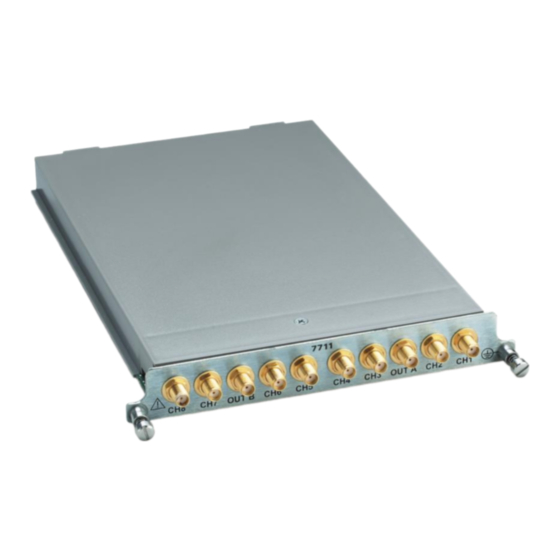
Model 7711 2 GHz 50 Ohm RF Module
Figure 1: Model 7711
*P077147600*
Instructions for use with DAQ6510
1
Advertisement
Table of Contents

Related Manuals for Tektronix Keithley 7711


Summary of Contents for Tektronix Keithley 7711
- Page 1 Model 7711 2 GHz 50 Ohm RF Module Keithley Instruments Instructions for use with DAQ6510 28775 Aurora Road Cleveland, Ohio 44139 1-800-935-5595 tek.com/keithley Introduction The 7711 plug-in module provides an economical, wideband signal routing solution that complements the DC/low frequency switching and measurement capability of the Model 7700 Switch Modules. The 7711 offers dual 1 ×...
-
Page 2: Installation
Model 7711 2 GHz 50 Ohm RF Module Instructions for use with DAQ6510 Installation Before operating an instrument with a switching module, verify that the switching module is properly installed and the mounting screws are tightly fastened. If the mounting screws are not properly connected, an electrical shock hazard may be present. - Page 3 Model 7711 2 GHz 50 Ohm RF Module Instructions for use with DAQ6510 Before installing or removing a switching module, make sure the DAQ6510 power is turned off and disconnected from line power. Failure to comply may result in incorrect operation and loss of data in the memory.
-
Page 4: Wiring Procedure
Model 7711 2 GHz 50 Ohm RF Module Instructions for use with DAQ6510 Before installing or removing a switching module, make sure the DAQ6510 power is turned off and disconnected from line power. Failure to comply may result in incorrect operation and loss of data in the memory. - Page 5 Model 7711 2 GHz 50 Ohm RF Module Instructions for use with DAQ6510 Do not touch live radio frequency (RF) conductors, even at low voltages. RF behaves differently than DC or low frequency AC. Low voltage RF can cause severe burns. RF signals spread out over body areas, generating substantial currents at the points of contact with RF conductors.
- Page 6 Model 7711 2 GHz 50 Ohm RF Module Instructions for use with DAQ6510 Expansion One switching module configuration is a dual 1 × 4 multiplexer. A single switching module can also be configured as a 4 × 4 blocking matrix. The switching module can be combined with additional modules to further expand its multiplexing and matrix switching capabilities.
- Page 7 Model 7711 2 GHz 50 Ohm RF Module Instructions for use with DAQ6510 Multiplexer examples SP8T MUX This example creates a 1 × 8 SP8T MUX (single-pole eight-throw multiplexer) using two switching modules. Channels 1 and 2 are connected to OUT A and OUT B of the second switching module in slot two. Terminate unused channels with a 50 Ω...
- Page 8 Model 7711 2 GHz 50 Ohm RF Module Instructions for use with DAQ6510 SP12T MUX To create a 1 × 12 SP12T MUX (single-pole 12-throw multiplexer) using two switching modules, channels 1 and 2 are connected to OUT A and OUT B of the second switching module in slot 2. Terminate unused channels with a 50 Ω...
-
Page 9: Measurement Considerations
Model 7711 2 GHz 50 Ohm RF Module Instructions for use with DAQ6510 Single switching module 4 × 4 blocking matrix This configuration provides a convenient way to connect four DUTs to four different test instruments. In this configuration, channels 1 to 4 may be routed to channels 5 to 8. Use a short coaxial cable to connect OUT A to OUT B. -
Page 10: Power Handling
Model 7711 2 GHz 50 Ohm RF Module Instructions for use with DAQ6510 Power handling The graph shows the maximum amount of power per channel that can be routed using the switching module while maintaining proper digital multimeter accuracy. Power levels of up to 10 watts at frequencies greater than 200 MHz can be used, but this may cause measurement errors. -
Page 11: Performance Verification
▪ Tektronix test port cables, Type-N(m) to Type-SMA(m), 1 m (012-1770-00) ▪ Tektronix 3.5 mm SOLT mechanical calibration kit 0 to 32 GHz, Spinner BN 53 38 54 (CALMECH-35MM) Prepare for verification To prepare for verification: 1. Turn on the network analyzer and the DAQ6510 with the switching module installed. - Page 12 Model 7711 2 GHz 50 Ohm RF Module Instructions for use with DAQ6510 VSWR To verify VSWR: 1. Connect network analyzer Port 1 to channel 1 and Port 2 to OUT A. 2. On the DAQ6510, close channel 1. 3. On the network analyzer, display the VSWR graph. 4.
-
Page 13: Insertion Loss
Model 7711 2 GHz 50 Ohm RF Module Instructions for use with DAQ6510 Insertion loss To verify insertion loss: 1. Connect network analyzer Port 1 to channel 1 and Port 2 to OUT A. 2. On the DAQ6510, close channel 1. 3. -
Page 14: Factory Service
Factory service To return the switching module to Keithley Instruments for repair: ▪ Call the Repair Department at 1-800-833-9200 or send an email to RMAREQUEST@tektronix.com for a Return Material Authorization (RMA) number. ▪ Carefully pack the instrument in the original packing carton. -
Page 15: Safety Precautions
Safety precautions The following safety precautions should be observed before using this product and any associated instrumentation. Although some instruments and accessories would normally be used with nonhazardous voltages, there are situations where hazardous conditions may be present. This product is intended for use by personnel who recognize shock hazards and are familiar with the safety precautions required to avoid possible injury. - Page 16 For safety, instruments and accessories must be used in accordance with the operating instructions. If the instruments or accessories are used in a manner not specified in the operating instructions, the protection provided by the equipment may be impaired. Do not exceed the maximum signal levels of the instruments and accessories. Maximum signal levels are defined in the specifications and operating information and shown on the instrument panels, test fixture panels, and switching cards.
Need help?
Do you have a question about the Keithley 7711 and is the answer not in the manual?
Questions and answers