Advertisement
- 1 General
- 2 Introduction
- 3 Mounting location guidelines
- 4 Prepare the back box
- 5 Fit the back box to the wall
- 6 Connection wiring
- 7 Power the device
- 8 Configuration
- 9 Check LED operation
- 10 Optional conventional interface card fitting
- 11 Connect the CIC to the CWIO
- 12 Fasten the CIC into the CWIO
- 13 Fasten the CWIOs terminals
- 14 Connection wiring
- 15 Specification
- 16 Documents / Resources

General
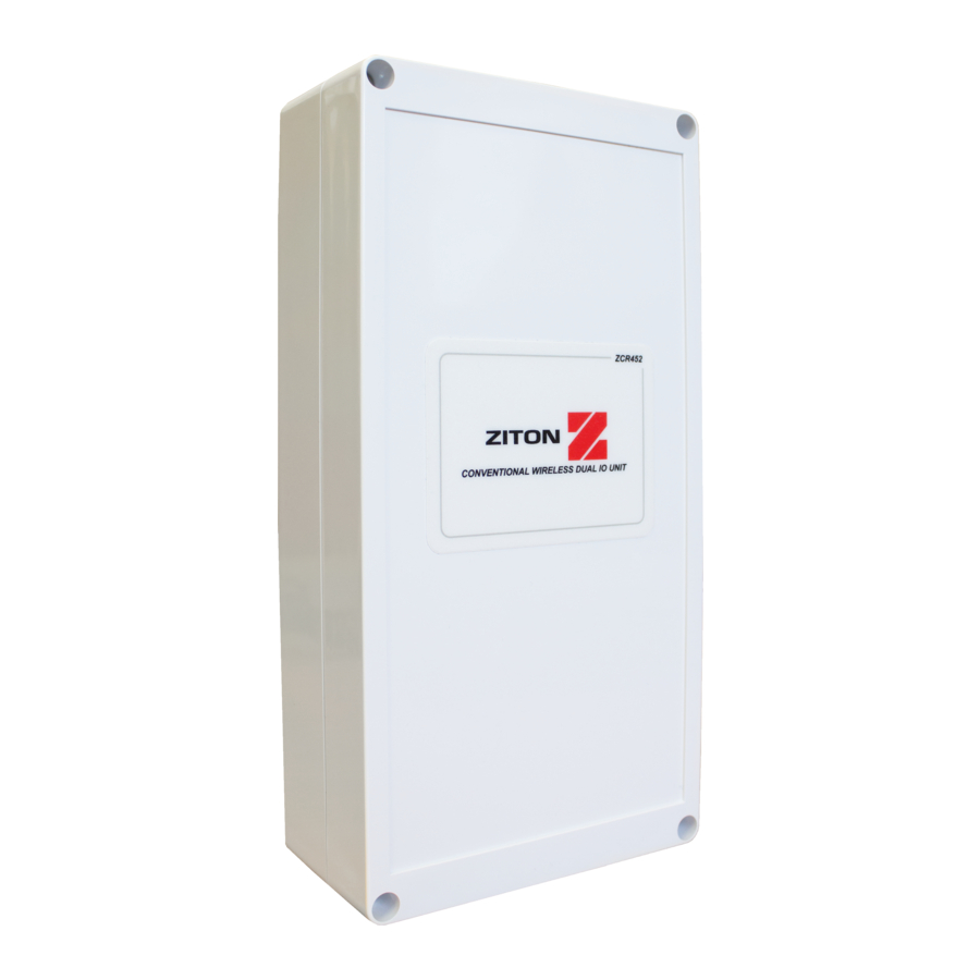
The Ziton conventional wireless dual IO (CWIO) unit is available under the following part number:
| PART NO | VARIANT TYPE |
| ZCR452 | Ziton conventional wireless dual IO unit |
Introduction
The address of the unit is set when programming the device to the Ziton conventional wireless communicator (see programming manual for details). The installation must conform to BS5839:Part 1 (or applicable local codes). The Ziton CWIO unit is suitable for indoor use only.
Ensure that all Ziton CWIO units are sited in accordance with the survey and design details. Mounting location guidelines
Mounting location guidelines

To ensure the optimum range performance of the CWIO unit is achieved, the following should be considered:
Ensure the CWIO and CWC are seperated by a minimum of 0.6m.
Ensure that the CWIO is not installed within 2m of the Control Panel or any other wireless or electrical equipment. See Figure 1.
Prepare the back box

Remove the four front plate retaining screws. Retain these for re-assembly when installation is complete. Remove the front plate.
Drill required cable entry points for the CWIO units cable connections. Recommended cable entry points are shown in Figure 2.
Fit the back box to the wall
Position the Ziton CWIO unit in the required location and mark the four fixing positions. These are shown in Figure 2.
Using suitable screws and fixings attach the device securely to the wall.
Connection wiring
Refer to the conventional wireless communicator programming guide for full wiring details (TSD146).
Power the device

To ensure correct operation, connect the power jumper across the PIN header on the PCB. The location of header is shown in Figure 3.
The Ziton CWIO unit is powered by 6 x AA alkaline batteries. These are supplied fitted. Should batteries require replacement, only use specified batteries whilst observing correct polarity as shown in Figure 3.
Configuration
The Ziton CWIO unit must be logged on to the CWC before adding other wireless devices to the system.
Refer to the conventional wireless communicator programming guide (TSD146), for full programming details.
Check LED operation

The device has six indication LEDs. Pressing the LED enable button enables their illumination for 10 minutes before automatically timing out.
Output LEDs: Each relay output has an associated red LED that will illuminate whilst the output is in an active state.
Input fault LEDs: Each input has an associated yellow fault LED that will illuminate whilst the input is in a fault condition.
Input switch closed LEDs: Each input has an associated red closed LED that will illuminate if the input is closed (alarm condition).
Optional conventional interface card fitting
The Ziton conventional interface card (CIC) when fitted to the Ziton conventional wireless i/o (CWIO), enables 30 Ziton wireless devices to be added to an existing Conventional fire alarm control panel, via a Ziton conventional wireless communicator (CWC).
The following points require consideration upon installation:
The CIC is only to be fitted to the CWIO, when connection is required to a Conventional fire alarm control panel.
The CIC should only be connected to designated zone and sounder circuits.
Refer to the Ziton conventional wireless communicator engineers guide (TSD146) for full programming information.
Connect the CIC to the CWIO

Ensure the pins line up with the ZIMs terminal connections as shown in Figure 5.
Fasten the CIC into the CWIO
 As shown in Figure 6.
Fasten the CWIOs terminals
 As shown in Figure 7.
Connection wiring
The CIC can be wired in two different ways.
Fault notification can either be monitored via the Conventional FAPs Sounder or Zone Circuit.
Refer to the Ziton conventional wireless communicator engineers guide (TSD146) for full details.
Specification
| Operating temperature | -10 to +70°C (ambient) |
| Operating temperature | 0 to +35°C |
| Humidity | Up to 95% non-condensing |
| Supply | 6x AA Alkaline (Panasonic LR6AD Powerline / Varta 4006 Industrial) |
| IP rating | IP65 |
| Output rating | 2A @ 24V DC |
| Operating frequencies | 868 MHz |
| Output transmitter power | Variable 0-14 dBm |
| Dimensions | 120mm (H) 240mm (W) 50mm (D) |
| Weight | 0.60kg |
Regulatory information
www.acornfi

Documents / ResourcesDownload manual
Here you can download full pdf version of manual, it may contain additional safety instructions, warranty information, FCC rules, etc.
Download Ziton ZCR452 - Conventional Wireless Dual IO Unit Installation Guide
Advertisement


Need help?
Do you have a question about the ZCR452 and is the answer not in the manual?
Questions and answers