Table of Contents
Advertisement
Quick Links
Advertisement
Table of Contents

Summary of Contents for RSE VMU-I
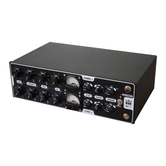
- Page 1 VMU-I tube compressor/limiter (variable gain) OWNER’S MANUAL...
-
Page 2: Table Of Contents
CONTENTS SECTION PAGE FROM HEAD OF TECHNOLOGY (Introduction) MAINS CONNECTION FUSE REPLACEMENT TUBES REPLACEMENT SIGNAL CONNECTION INSTALLATION OPERATIONAL NOTES & ADJUSTMENTS TESTING & TROUBLESHOOTING GAIN REDUCTION CURVES SPECIFICATIONS... -
Page 3: From Head Of Technology (Introduction)
From head of technology (INTRODUCTION) Dear valued customer, Thank you for choosing our device. We're proud of crafting each piece of gear with care and dedication from our team in Ukraine. Our VMU-1 compressor is designed to expand your possibilities and remove limitations you may have faced before. A vari-mu compressor is a type of analog compressor that uses vacuum tubes to control the gain reduction of the signal. -
Page 4: Mains Connection
MAINS CONNECTION The RSE VMU-1 compressor can be powered with either a 230V or 110V grid. It is important to note that the voltage is predefined by the manufacturer and cannot be adjusted operatively. To ensure safe and proper operation of the device, please follow these guidelines when connecting it to the mains: 1. -
Page 5: Fuse Replacement
FUSE REPLACEMENT In the event that the fuse in your RSE VMU-1 compressor needs to be replaced, it is important to use a 3A/250V slow fuse. To replace the fuse, follow these steps: 1. Unplug the power cord from the AC outlet and disconnect it from the VMU-1. -
Page 6: Tubes Replacement
TUBE REPLACEMENT The RSE VMU-1 has a fully balanced tube schematic which includes three types of tubes: (1) ECC85 - used as a vari-gain element (2) 6N6P (ECC99) - used in output stage (3) EСС81 (used in detector stage) These tubes are essential components of the device, and they need to be replaced periodically to ensure optimal performance. -
Page 7: Signal Connection
SIGNAL CONNECTION The RSE VMU-1 compressor is equipped with fully balanced XLR connectors for input and output connections. The use of XLR connectors is preferred due to their sturdy design and ability to provide a reliable balanced connection. The standard color coding for XLR connectors is as follows:... -
Page 8: Installation
INSTALLATION To install the RSE VMU-1 compressor into a 19" rack, follow these steps: 1. Ensure that the compressor is powered off and unplugged from any power source. 2. Remove any protective packaging or covers from the compressor. 3. Install the mounting ears to the VMU's main chassis using screws from a set. -
Page 9: Operational Notes & Adjustments
OPERATIONAL NOTES & ADJUSTMENTS The front panel of the RSE VMU-1 compressor is designed to provide easy access to all the necessary controls for adjusting the sound output. The Gain (1) knob is used to adjust the input level of the signal, which can be increased or decreased depending on the desired output. - Page 10 The Power button and Power light (10) indicator are also located on the front panel, allowing you to easily turn on and off the compressor and monitor its status. Overall, the front panel of the RSE VMU-1 compressor is well-designed and intuitive, providing easy access to all the necessary...
-
Page 11: Testing & Troubleshooting
TESTING & TROUBLESHOOTING To check the device works correctly do next steps: 1. Set the Gain and Out knobs to the “0” positions 2. Set the Threshold knob to the extreme clockwise position (100%) 3. Set the Ratio knob to the extreme counterclockwise position (0%) 4. - Page 12 3. I believe, the tubes inside needed to be replaced. Which types I can use to do this? - Please, notice, that all tubes inside are matched pairs and tube swapping can lead to the schematic's unbalancing, even while tubes have the same marking. Also, note that the plate voltage is dangerous, so it's not recommended to do it yourself.
-
Page 13: Gain Reduction Curves
GAIN REDUCTION CURVES Soft-knee signal compression is a type of compression that gradually reduces the gain of an audio signal as it approaches a certain threshold. Unlike hard-knee compression, which applies a fixed amount of gain reduction once the threshold is reached, soft-knee compression offers a more gradual and natural-sounding reduction in volume. -
Page 14: Specifications
SPECIFICATIONS - Custom built amorphous-core RSE input & output transformers - 20Hz-20kHz (+/-3dB) frequency response - BALANCED INPUTS & OUTPUTS (600 Ohms) - Fully differential ALL-TUBE circuitry using one each ECC85, 2*6N23P per channel - Stabilized plate voltage - Stabilized Heater voltage...
Need help?
Do you have a question about the VMU-I and is the answer not in the manual?
Questions and answers