Table of Contents
Advertisement
Quick Links
Advertisement
Table of Contents

Summary of Contents for Mex Veronte AVIONICS
- Page 1 MEX Hardware Manual Release 1.0 Embention 2023-06-15...
-
Page 3: Table Of Contents
3.2.2 MEX OEM version ........ - Page 5 MEX Hardware Manual, Release 1.0 CONTENTS...
- Page 6 MEX Hardware Manual, Release 1.0 CONTENTS...
-
Page 7: Introduction
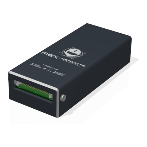
Fig. 1: Veronte MEX Veronte MEX stands as a powerful peripheral to ease the reduction of wire in autonomous vehicles at the time it allows to increase the number of devices in the system. It makes possible to relocate and to group sensors, actuators, payloads, motor controllers. -
Page 8: Wiring Optimization
This upgrade is achieved thanks to the reduction of cable length and because of the added flexibility so the right device can be installed in the right location. Another advantage of the use of Veronte MEX is the robustness of the CAN Bus, being resistant to electromagnetic interferences and permitting the installation of long cables with no signal loss. -
Page 9: Quick Start
– Magnets or magnetic fields. – Electric or electronic devices (for example electric motors or antennas). • Veronte MEX will always produce heat as a by-product of its operation. Keep in mind an adequate heat dissipation on installation. • To disconect cables from the connector of the OEM version, a G125 Delatching Tool Separator is recommended, referenced as Z125-9263400. -
Page 10: Requirements
MEX Hardware Manual, Release 1.0 2.2 Requirements Required items: • Veronte Link (version 6.12.X or higher). • MEX PDI Builder (version 6.10.X or higher). • Veronte Autopilot (version 6.8.X or higher). • Veronte Updater (version 6.8.X or higher). Chapter 2. Quick Start... -
Page 11: Technical
TECHNICAL 3.1 Variants Veronte MEX is offered with two versions: MEX and MEX OEM. The MEX version is protected by an enclosure made of anodized-aluminium. The MEX OEM version is smaller, lighter and has better heat dissipation; but requires mechanical protection when installed. -
Page 12: Part List
MEX Hardware Manual, Release 1.0 Fig. 2: MEX OEM version 3.2 Part List 3.2.1 MEX version 1. Cable connector. Embention reference: P006354. Commercial reference: G125-FC13405L0-0450L. Chapter 3. Technical... -
Page 13: Mex Oem Version
MEX Hardware Manual, Release 1.0 2. MEX. 3.2.2 MEX OEM version 1. Cable connector. Embention reference: P006354. Commercial reference: G125-FC13405L0-0450L. 2. MEX OEM. 3.3 Features • Communications – 2x isolated CAN busses – 2x RS-232 buses for external devices – 1x full-duplex RS-485 interface –... -
Page 14: Magnetometer
MEX Hardware Manual, Release 1.0 • Signals – 4x PWM output signals with electrostatic discharge protection (IEC-61000-4-2, level 4), between 10 Hz to 10 kHz – 4x analog input signals – 2x digital input signals of ECAP, EQEP or GPIO (only as input) •... -
Page 15: Mechanical Specifications
4x M2 screws (2 of them must not be ferrous) 3.6.1 Dimensions MEX version Veronte MEX is protected by an enclosure made of anodized-aluminium 6061-T6. M3 aluminum or nylon screws are recommended as mounting hardware for better magnetometer performance. Enclosure mounting holes are 4mm depth M3 threaded. - Page 16 MEX Hardware Manual, Release 1.0 Fig. 3: MEX dimensions MEX OEM version Chapter 3. Technical...
-
Page 17: Interfaces
MEX Hardware Manual, Release 1.0 Fig. 4: MEX OEM dimensions 3.7 Interfaces There is only one interface connection, with the two following connectors: 3.7. Interfaces... - Page 18 MEX Hardware Manual, Release 1.0 Fig. 5: Interface connection Number Connector Embention reference Commercial reference Female P006354 G125-FC13405L0-0450L Male P006723 G125-MH13405L3P Chapter 3. Technical...
-
Page 19: Hardware Installation
CHAPTER FOUR HARDWARE INSTALLATION Version Fixation 2x M3 screws MEX OEM 4x M2 screws (2 of them must not be ferrous) 4.1 Pinout Pins are arranged as follows: PIN Nº Comments Power supply 1 Power supply for the main system, redundant with Power supply 2... - Page 20 MEX Hardware Manual, Release 1.0 Table 1 – continued from previous page PIN Nº Comments ANALOG (3) 12V Analog input 0-12 V ANALOG (4) 36V Analog input 0-36 V Ground for supply ECAP 1 ECAP, EQEP or GPIO (only as...
-
Page 21: Electrical Diagram Of Can Bus
Fig. 1: CAN assembly diagram example Veronte MEX has an internal resistor of 120 , which can be activated by SW. Then, another way to connect multiple CAN Bus devices lies in connecting a MEX to the end of cables, then activating its internal CAN resistor. - Page 22 MEX Hardware Manual, Release 1.0 Chapter 4. Hardware Installation...
-
Page 23: Software Installation
• Via Autopilot 1x It is usual to have a MEX in a system that does not allow to directly connect to a PC. In that situation, it is possible to configure an Autopilot 1x that is connected over CAN with MEX. To establish a connection between... - Page 24 MEX Hardware Manual, Release 1.0 Chapter 5. Software Installation...
-
Page 25: Maintenance
CHAPTER MAINTENANCE 6.1 Preventive Maintenance Apart from cleaning, no extra maintenance is required to guarantee the correct operation of the Veronte MEX. In order to clean Veronte MEX properly follow the next recommendations: • Turn off the device before cleaning. - Page 26 MEX Hardware Manual, Release 1.0 Chapter 6. Maintenance...
-
Page 27: Troubleshooting
For forcing Maintenance mode, create a loopback on both I2C pins (I2C SCL and I2C SDA signals). When powered, MEX will boot in maintenance mode. - Page 28 MEX Hardware Manual, Release 1.0 Chapter 7. Troubleshooting...
-
Page 29: Acronyms And Definitions
CHAPTER EIGHT ACRONYMS AND DEFINITIONS Battery Eliminating Circuit Controller Area Network COMmunications Direct Current EQEP Enhanced Quadrature Encoder Pulse sensor Electronic Speed Control ElectroStatic Discharge Electrical ground GPIO General Purpose Input/Output Input/Output JTAG Joint Test Action Group Mbps Megabits Per Second Micro-Processor Unit NanoTesla Original Equipment Manufacturer... - Page 30 MEX Hardware Manual, Release 1.0 Chapter 8. Acronyms and Definitions...
-
Page 31: Contact Data
CHAPTER NINE CONTACT DATA You can contact Embention in any moment if you need further help and support. Embention contact data is as follows: Email: support@embention.com Telephone: (+34) 965 421 115 Address: Polígono Industrial Las Atalayas, C/ Chelín, Nº 16, CP 03114, Alicante (España).
Need help?
Do you have a question about the Veronte AVIONICS and is the answer not in the manual?
Questions and answers