Advertisement
INTRODUCTION
The SP-600 is a passing power meter which is connected between a transmitter and antenna for measuring directly the transmitted power, reflected power and the SWR of the antenna system by transmitting a carrier.
The SP-600 has a high sensitivity and high performance power sensor featuring flat frequency characteristics over a wide range, and this power sensor, developed by WELZ, permits accurate measurement of power and SWR with minimum of measuring error.
The SP-600 is a wide band measuring equipment covering a range of 1.6 to 500 MHz. This equipment has three built-in power sensors, and is capable of measuring simultaneously three transmitting antenna systems.
FEATURES
- These sensors permits big power measurement, 2kW for HF band, 200W for other frequencies.
- Meter lighting and LED indicators permit measurement at dark place (outside DC 12V power supply).
- Three wide band sensors (directional couplers) having superior frequency characteristics are built in this meter. These wide band sensors, developed originally by WELZ, permits simultaneous measurement of three systems of any band of HF, VHF and UHF bands.
- The meter permits selection among three ranges of 20W, 200W, and 2,000W.
- The minimum SWR measuring sensitivity is 1.5W for RS1, and 1W for RS 2, and 2W for RS 3.
- The meter body is surrounded by double or triple shielding case for eliminating error due to diffraction of high frequency waves. This meter is therefore free from measuring error due to induction which is often encountered in meters housed in a plastic casing.
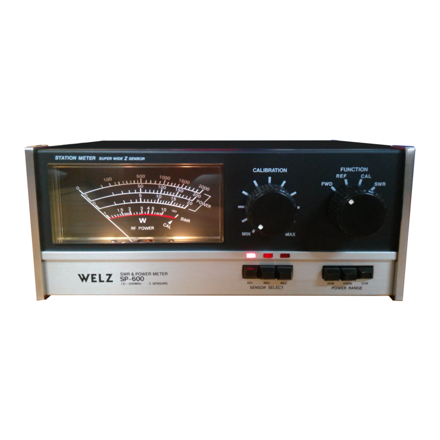
NAMES OF PARTS AND FUNCTIONS

- Meter
This meter indicates the SWR value, transmitted power, and reflected power. The lower red scale is for SWR reading, and the upper three scales for indication of power value. The power scales are provided in three different ranges of 2kW, 200W, and 20W, which can be selected by means of the range selector switch. Both the SWR value and power value can be read directly on the meter scale, and no correction table nor frequency characteristics correction knob is needed. - "RANGE"- switch
This switch is used to change the full scale value on the meter for power indication to 2kW, 200W and 20W. - "FUNCTION" switch
Set this switch to "FWD" (forward power) position when reading the transmitted power on the meter, and to "REF" (reflected power) position when reading the reflected power. To measure the SWR value, first set the transceiver in the carrier sending status, and set the switch to "CAL" position. Then turn the calbration knob, until the needle comes up to the position of CAL A, and change the function switch-to "SWR" position. The SWR value can then be read directly on the meter. - "CAL" knob
This knob is used to set the meter corresponding to the power when measuring the SWR value. If turned clockwise, the needle will move to the right; if turned counterclockwise, the needle will move to the left. Turn the knob until the needle is aligned correctly with CAL A position. - "SENSOR SELECT" switch
This switch is used to select the DC output detected by three sensors located on the rear side of this meter. RS1 is for measurement within the range of 1.6 — 60MHz, RS2 for measurement within 1.8 — 200MHz and RS3 within 130 — 500MHz. Since the detected output can be switched over among RS1, RS2 and RS3, three antenna systems can be compared in the simultaneous transmission state. - Sensor Select Display LED.
LED, illuminated by an external power source (DC + 10 to 15V), displays the sensor of the transmission system being measured.

- Name plate
- Pass seal
- "RS1.TX" connector
An SO-239 connector for connecting input to the sensor"RS1."Connect a transmitter of 1.6 — 60MHz and less than 2kW to this connector. - "RS1.ANT" connector
An SO-239 type connector for connecting output of the sensor "RS1." Connect an antenna or dummy load, or other loading device of 1.6 — 60MHz to this connector. - "RS2.TX" connector
An SO-239 type connector for connecting input to the sensor "RS2." Connect a transmitter of 1.8 — 200MHz and less than 200W to this connector. - "RS2.ANT" connector
An SO-239 type connector for connecting output of the sensor "RS2." Connect an antenna, dummy load, or other loading device of 1.8 — 200M Hz. - "RS3.TX" connector
connection with a transmitter rated less than 200W over the range of 130 to 500MHz. - "RS3.ANT" connector
SO-239 type connector serving as an input of Sensor RS3. Designed for connection with antenna, dummy load or any other load equipment rated at less than 200W over the range of 130 to 500MHz. - External Power Source Connection Terminal.
Designed for meter lighting or to illuminate sensor display LED. Connection should be made with the power source (DC 12V to 15V), ensuring the proper polarities. When light is turned off or not in use, be sure to pull the plug from the power source. Note that this power source has no relation with measurement functions.
BEFORE USING
- Measurement of transceiver power and SWR with this meter requires a connecting cable. In such measurement, be sure to use a 50-ohm coaxial cable, with connectors attached securely to both ends.
- For accurate measurement of power, prepare a reliable dummy load having SWR of less than 1.1.
- This meter has been adjusted completely in the factory before shipping. Removal of the case, or tampering the internal components may cause measusrement error, and must therefore be avoided.
- The packing materials (and corrugated cardboard box) used for packing this meter may also be utilized for protection of the meter when ordering repair or maintenance service. It is recommended to keep the corrugated cardboard box together with'the instruction book.
OPERATION PROCEDURE
- The SP-600 permits simultaneous connection of three transmitters and 3 antennas. Make suitable connection to RSI, RS2 or RS3 on the rear panel, corresponding to the frequency and sending power of the transmitter to be measured.
- After completing connection of the transmitters and antennas, select a transmitter and antenna to be measured by using the "SENSOR SELECT" switch for measuring the power and SWR value.

- Measurement of forward power (FWD)
- Set the "FUNCTION" switch to "FWD" position.
- Set the "RANGE" switch to a proper power range corresponding to the power to be measured.
- Send out carrier from the transmitter or transceiver; the meter will indicate the forward power.
- Measurement of reflected power (REF) (
- Set the "FUNCTION" switch to "REF" position.
- Set the "RANGE" switch to a proper power range corresponding to the power to be measured.
- Send out the carrier from the transmitter or transceiver; the meter will indicate the reflected power.
- Measurement of effective radiation power (ERP)
The difference between forward power and reflected power is the effective radiation power. (Example)
If "FWD" reading is 100W and "REF" reading is 4W, the effective radiation power is 100 — 4 = 96W.

- Measurement of SWR
- Set the "FUNCTION" switch to "CAL" position.
- Send out the carrier from the transmitter; the meter will deflect to a certain position.
- Turn the CAL knob, and align the meter needle with the CAL', position.
- Next, change the "FUNCTION" switch to the SWR position. The meter needle will indicate an SWR value. This is the SWR of the antenna.
- The SWR can also be obtained from the following equation.


For example, if Pf = 100W and Pr = 4W, then SWR can be calculated as follows:

- Precautions
- Note that the measurable frequency range of this meter is 1.6 to 60MHz for RS1, 1.8 to 200MHz for RS2 and 130 to 500MHz for RS3. No accurate measurement can be made for other frequencies because of increased indication error.
- The maximum measurable power is 2kW for RS1 and 200W for RS2 and RS3. Do not apply larger power exceeding this value, otherwise, the sensor might be burnt and damaged due to overheating.


SPECIFICATIONS
| Rating | SP-600 | ||
| RS 1 | RS 2 | RS 3 | |
| Frequency range (MHz) | 1.6 — 60 | 1.8 — 200 | 130 — 500 |
| Measurable power (W) | 0 — 2,000 | 0 — 200 | 0 — 200 |
| Power measurement accuracy | ±10% (F.S. value) | ||
| Power measuring range | 20/200/2,000 f | 20/200 1 | 20/200 |
| Measuring functions | Forward power (FWD), Reflected power (REF), V.S.W.R. (SWR), SWR calibration (CAL) | ||
| Sensor selection | Built-in 3 sensor selection (RS 1, RS 2, RS 3) | ||
| Insertion loss | 0.1 | 0.1 | 0.25 |
| SWR measuring sensitivity (W) | 1.5 | 1 | 2 |
| SWR measurement | 1:1 — 1: | ||
| Impedance (S2) | 50 | ||
| Connector (Type) | SO-239 | ||
| Dimensions (mm) | 220(W) x 91(H) x 113(D) | ||
| Weight (kg) | 1.75 | ||
Circuit diagram

* Above specifications are subject to change without notice.
* Patents on sensor circuitry and registration of new design are now pending.

Documents / ResourcesDownload manual
Here you can download full pdf version of manual, it may contain additional safety instructions, warranty information, FCC rules, etc.
Advertisement

Need help?
Do you have a question about the SP-600 and is the answer not in the manual?
Questions and answers