
Summary of Contents for Panametrics TMO2D
- Page 1 Process Analyzers TMO2D Digital Display User’s Manual 910-084 D panametrics.com August 2021...
- Page 3 Process Analyzers TMO2D Digital Display User’s Manual 910-084 Rev. D August 2021 panametrics.com Copyright 2021 Baker Hughes company. This material contains one or more registered trademarks of Baker Hughes Company and its subsidiaries in one or more countries. All third-party product and company names are trademarks of their respective...
- Page 4 [no content intended for this page]...
- Page 5 Make sure that operators and maintenance personnel have all safety equipment applicable to the auxiliary equipment. Examples include safety glasses, protective headgear, safety shoes, etc. Unauthorized Operation Make sure that unauthorized personnel cannot gain access to the operation of the equipment. TMO2D User’s Manual...
- Page 6 Environmental Compliance Waste Electrical and Electronic Equipment (WEEE) Directive Panametrics Solutions is an active participant in Europe’s Waste Electrical and Electronic Equipment (WEEE) take-back initiative, directive 2002/96/EC. The equipment that you bought has required the extraction and use of natural resources for its production. It may contain hazardous substances that could impact health and the environment.
-
Page 7: Table Of Contents
Wiring Other Components to the TMO2D Display ........ - Page 8 Ordering Information ...................65 Appendix A. Outline and Installation Drawings Appendix B. Menu Maps TMO2D User’s Manual...
-
Page 9: Chapter 1. Features And Capabilities
Chapter 1. Features and Capabilities Overview This chapter presents the features and capabilities of the TMO2D Digital Display. It also includes a brief list of Panametrics transmitters that can be used with the TMO2D Digital Display. Introduction The TMO2D Digital Display offers a number of important features: •... - Page 10 Chapter 1. Features and Capabilities [no content intended for this page] TMO2D User’s Manual...
-
Page 11: Chapter 2. Installation
2.3.1 TMO2 Transmitter This section describes how to interconnect the TMO2 and TMO2D. The TMO2 can be wired for internal or external compensation. Each type of compensation requires a different cable. Before you make any connections, make sure you have the appropriate cable. Please check the TMO2 calibration sheet to determine if your TMO2 has internal or external compensation. - Page 12 Tighten the side screws, and carefully plug TB1 back onto the TMO2 PCB. Connect the other end of the cable in a similar manner to the TMO2D. Refer to Figure on page 17 for TB1 location. TMO2D User’s Manual...
- Page 13 Chapter 2. Installation +24 V/1 AMP 1 Black Return 2 White Gas 3 Green/Blue Comp. 4 Signal Connections Figure 1: Wiring Connections to TB1 Block CAUTION! Do not make any connections to unassigned or unused terminals. TMO2D User’s Manual...
- Page 14 If you make the modifications as discussed here, your unit will comply with the EMC Directive 2004/108/EC. Note: For CE compliance, the I/O cables must be shielded. The shields are to be grounded within the TMO2D to the closest location.Shielded cable is not required when installations include metal conduit.
-
Page 15: Xmo2 Transmitter
XMO2 Transmitter Wiring the XMO2 oxygen transmitter to the TMO2D display requires use of the X4(*) cable, which can support distances up to 450 ft (130 m). For longer distances, each cable can be supplied as 18-AWG that can be located up to 1,050 ft. - Page 16 Tighten the side screws, and carefully plug terminal block TB1/TB2 back onto the XMO2 PCB. Connect the other end of the cable in a similar manner to the TMO2D. Refer to Figure on page 17 for the TB1 location.
- Page 17 Internal Ground Screw External Ground Screw Cover +24VDC Line (red) 1 –24VDC Return (black) +4 to 20mA (white) –4 to 20 mA (green) RS232 RX (red) 1 RS232 TX (white) RS232 GND (green) Figure 5: XMO2 Wiring Connections TMO2D User’s Manual...
-
Page 18: Tmo2-Tc Transmitter
It could also cause damage to the TMO2-TC PCB, requiring factory repair. Tighten the side screws, and carefully plug TB1 onto the PCB. Connect the other end of the cable in a similar manner to the TMO2D. Refer to Figure on page 17 for TB1 location. TMO2D User’s Manual... - Page 19 Note: If you make the modifications as discussed here, your unit will comply with the EMC Directive 2004/108/EC. For CE compliance, the I/O cables must be shielded. The shields are to be grounded within the TMO2D to the Note: closest location. Shielded cable is not required when installations include metal conduit.
-
Page 20: Xmtc Transmitter
XMTC Transmitter Connecting the XMTC thermal conductivity transmitter to the TMO2D requires use of the X4(*) or Y4(*) cables. The X4(*) cable can be used for distances up to 450 ft (130 m). For longer distances, each cable can be supplied as 18-AWG that can be located up to 1,050 ft (320 m). - Page 21 If you make the modifications as discussed here, your unit will comply with the EMC Directive 2004/108/EC. Note: For CE compliance, the I/O cables must be shielded. The shields are to be grounded within the TMO2D to the closest location. Shielded cable is not required when installations include metal conduit.
- Page 22 +24 VDC Line (red) 1 –24 VDC Return (blk) 2 +4 to 20 mA (white) 3 –4 to 20 mA (green) 4 RS232 RX (red) 1 RS232 TX (white) 2 RS232 GND (green) 3 Signal Connections Figure 9: XMTC Wiring Connections TMO2D User’s Manual...
-
Page 23: Rs-232C Serial Port
RS-232C protocol. Connect the RS-232C from the computer or terminal to the rear of the TMO2D using a 25-pin connector. (See Figure 10 below for the RS-232 wiring pin connections, and Chapter 3 for the corresponding key chart.) - Page 24 Chapter 2. Installation [no content intended for this page] TMO2D User’s Manual...
- Page 25 Chapter 2. Installation TMO2D User’s Manual...
- Page 26 Chapter 2. Installation TMO2D User’s Manual...
-
Page 27: Chapter 3. Operation
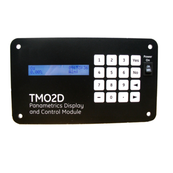
The interconnecting wiring between the transmitter and display must be completed before powering To power up the benchtop TMO2D, press the red power key to the right of the display. Other TMO2D models have no power switch, and begin operating when the external power to which they have been connected has been turned on. -
Page 28: The Keypad
Figure 12: The TMO2D Display RS-232C Serial Port The TMO2D contains a bidirectional, industry-standard RS-232C serial port which can be connected to a terminal or computer that supports the RS-232C protocol (see The Outputs Menu on page 30.) All keypad and most display operations can be performed remotely through this serial port. -
Page 29: Chapter 4. Basic Programming
This user program has six main menus. Use the front panel keypad and display to check or change the settings for current operating parameters. The TMO2D stores data in memory and will retain it for several years if the main power is lost. -
Page 30: Key Functions
The [] key enables you to scroll forward through the menu options; it is equivalent to pressing the [NO] key in the Menu Mode. Programming the TMO2D Using the Display This section briefly explains display and menu navigation, and then takes you step-by-step through the programming procedure. -
Page 31: Menu Navigation
These submenus allow you to alter operating parameters. Once entered, these values remain in the display memory until you change them. (Appendix B offers a flow diagram of the Setup Menu in Figure 26 on page 82.) TMO2D User’s Manual... -
Page 32: Set Time
%, the input scale (if used with an O2X1), and the measurement units and input range for the input gas. SETUP MENU Press [YES] to set the input gas, units and scale. Set Gas/Units/Scaling? TMO2D User’s Manual... -
Page 33: Set Backlight
If you have selected one of the five preprogrammed gases, the program returns to the Set Gas/Units/Scaling? submenu. However, if you have selected OTHER , the TMO2D asks for a gas label. A specific label can contain up to 8 characters. -
Page 34: Set Contrast
4.4.6 Set Display? Although this feature is not commonly used, the TMO2D, when used with the TMO2, can display compensation values for pressure or the percentage of background gas. For the analyzer to display these values, the TMO2 must include external compensation. -
Page 35: Set Communications
The baud rate can be changed using a terminal connected to the RS-232C port. However, this is not recommended, as the TMO2D will immediately change to the new baud rate. Display and keyboard operation will not be correct until the baud rate of the terminal is changed to match the new baud rate set in the TMO2D. - Page 36 SET COMMUNICATIONS Press [NO] to proceed to the next submenu. Set Time Stamp? SET COMMUNICATIONS Press [YES] to return to the main Setup Menu. Done? SETUP Menu Press [NO] to proceed to the next submenu. Set Communications? TMO2D User’s Manual...
-
Page 37: Set Error Handling
The Set Error Handling? submenu enables the TMO2D to handle inputs it receives that are outside its measurement range. Based on directions it receives, the TMO2D can show the errors on the display and force an output high or low. -
Page 38: The Outputs Menu
The TMO2D provides a choice of one isolated 0/4-20 mA output, or two isolated 0/4-20 mA outputs. You can set both options for a 0 to 20-mA or a 4-20 mA response, and scale the output anywhere within the range of the transmitter. -
Page 39: The Relays Menu
The Relays Menu The third main menu is the Relays Menu. The TMO2D includes two or four single-pole double throw (SPDT) relays for use in activating alarm devices or driving automatic calibration solenoid valves. The display addresses the relays as A, B, C or D. -
Page 40: Autocalibration Type
[ALARM] autocalibration 4.6.1 Autocalibration Type If you select Autocalibration, the TMO2D asks for the Auto-Calibration option: Auto-Cal Relay Type: Use the [NO] or arrow keys to select the autocalibration type, and press [YES] to confirm the selection. [PROC/CAL] zero/span For either selection, the program returns to the Select Relay to Set? entry. - Page 41 Press [NO] to proceed to the cal error action entry. Set System Fault Action? The calibration error could occur if the TMO2D performs an autocal on a transmitter and the amount of drift exceeds a programmed limit. You can set the limits in Change AutoCal Limits? on page 61.
- Page 42 The Cal occurred alarm trips if autoverification is enabled and an automatic calibration is performed on a transmitter. If the amount of drift exceeds the limits programmed, the TMO2D stores the new drift calibration data and trips an alarm to indicate the change. For further details, refer to page 43 and Change AutoCal Limits? on page 61.
-
Page 43: The Tests Menu
Press [NO] to proceed to the compensation signal test. Gas Input? Select DVM Input: Press [YES] to enter the compensation signal test. Comp Input? The compensation signal input is only used on a TMO2 oxygen transmitter with external background gas or external atmospheric pressure compensation. TMO2D User’s Manual... - Page 44 Press any key to return to the DVM submenu. X.XX mA 4.7.1.1 Done? Select DVM Input: Press [NO] to scroll to “Done?” and press [YES] to exit the DVM test. Done? TESTS Press [NO] to proceed to the Output submenu. DVM Test? TMO2D User’s Manual...
-
Page 45: Output Test
Select Relay to test: Use the [NO] or arrow keys to select A, and press [YES] to confirm the selection. [A] B done If you select a calibration relay to test, the TMO2D displays the following warning: Note: TMO2D User’s Manual... -
Page 46: The Calibration Menu
• Select Response? • Select Compensation? • Gas Calibration? • Pressure Calibration? • Auto Cal Parameters? (Refer to Figure 28 on page 84 and Figure 29 on page 85 for a flow diagram of the Calibration Menu.) TMO2D User’s Manual... -
Page 47: Select Response
Pressure — refer to page 40. • Background — refer to page 41. CALIBRATION MENU Press [YES] to enter the “Gas Calibration?” submenu. The menu will vary according to the selection made in the “Select Compensation?” submenu. Gas Calibration? TMO2D User’s Manual... - Page 48 4.8.3.2 Pressure Compensation: In the TMO2D, pressure (PRES) compensation is typically used only with a TMO2 oxygen transmitter. Pressure compensation will correct the oxygen readings for any changes in atmospheric pressure. If you have selected pressure compensation, you must enter both transducer data and pressure grid data.
-
Page 49: Pressure Calibration
Pressure Calibration? The Pressure Calibration? submenu enables users to directly calibrate the pressure transducer. While this menu option is always displayed, it should only be programmed and used when the TMO2D is used with a TMO2 calibrated for atmospheric pressure compensation. -
Page 50: Auto Cal Parameters
At the specified time interval, the TMO2D activates a solenoid valve on a sampling system using one of the relays provided. This procedure isolates the transmitter from the process stream and connects the transmitter to one of the calibration gases. - Page 51 Auto verification is similar to automatic calibration. The solenoids are still tripped to allow the calibration gases to flow to the transmitter. However, if the calculated drift is less than a preprogrammed amount, the TMO2D will not store the new drift data into memory. If the drift is beyond the verification limit and no cal error occurs, then the TMO2D applies new calibration data and sets a new calibration flag.
- Page 52 Use the [NO] or arrow keys to select enabling or disabling of auto cal verification. Press [YES] to confirm your entry. disabled [ENABLED] AUTO CALIBRATION MENU Press [NO] to proceed to the Time Interval option. Set Auto Verification? TMO2D User’s Manual...
- Page 53 [YES] twice to confirm the entry. Press [NO] to proceed. (The X’s represent the Days to Next Cal:[XX.XX] previously entered days.) Note: The number of days entered at this prompt can be no higher than the number of days entered at the “Days” prompt above. TMO2D User’s Manual...
- Page 54 For example, to set the zero gas in a 2-gas cal mode for 0.00% oxygen for an equilibration time of 3 minutes: AUTO CALIBRATION MENU Scroll through the submenu, and press [YES] to enter the Set Zero Gas option. Set Zero Gas? TMO2D User’s Manual...
- Page 55 AUTO CALIBRATION MENU Press [NO] to proceed to the Set Settling Time option. Set Span Gas? In the 1-gas cal mode, entering offset gas data is similar to entering the zero or span gas data described Note: above. TMO2D User’s Manual...
- Page 56 TMO2D resumes taking measurements and reactivates the recorder output. (During an autocal, the recorder output from the TMO2D has been locked to the last value it had sent directly before the autocal began.) AUTO CALIBRATION MENU Scroll through the submenu, and press [YES] to enter the Set Settling Time option.
- Page 57 Press [NO] to proceed to the next item. Set Output Response? AUTOCAL ERROR EFFECTS Press [YES] to exit the Error Effects submenu. Done? AUTO CALIBRATION MENU Press [NO] to proceed to the Perform Auto Cal? option. Set Error Handling? TMO2D User’s Manual...
- Page 58 At the end of the Auto Cal procedure, the Process/Cal relay will reset to the Process position and the settling time will count down to zero. The display will then read AutoCal in Progress and the TMO2D will return to the start of the Perform Auto Cal? option.
- Page 59 AUTO CALIBRATION MENU After counting down the settling time, the display returns to the start of the “Perform Auto Cal?” option. Press [NO] to proceed to the “Reset Drift?” option. Perform AutoCal? TMO2D User’s Manual...
- Page 60 Then press [NO] to exit the Auto Cal Parameters submenu. Auto Cal Parameters? 4.8.5.9 Done? CALIBRATION MENU Press [YES] to exit the Calibration Menu and return to the Main Menu. Done? MAIN MENU Press [NO] to proceed to the System Log menu. Calibration? TMO2D User’s Manual...
-
Page 61: The System Log Menu
Testing the fault alarm does not appear in the System Log. The TMO2D stores only the 25 most recent events in its memory. When additional events occur, the TMO2D discards the oldest event from the log to make room for the new event. Refer to Figure 29 on page 85, for a flow diagram of the System Log menu. -
Page 62: Viewing The System Log
The System Log may be viewed on the TMO2D display, or transmitted to a computer, printer or other data acquisition system using the RS232 serial port. To view the System Log on the TMO2D display, scroll through the Main Menu until... -
Page 63: Print System Log
To print the System Log or transmit it over the RS232 serial port: SYSTEM LOG MENU Press [YES] and the TMO2D transmits the entire log using the RS232 serial port. Print System Log? A System Log printout appears similar to the example shown in Figure 15 below. - Page 64 Chapter 4. Basic Programming [no content intended for this page] TMO2D User’s Manual...
-
Page 65: Chapter 5. Advanced Programming
Chapter 5. Advanced Programming 5.1 Introduction In addition to its basic program, the TMO2D analyzer contains a factory setup program that enables the user to perform more advanced operations on the parameters that have been first installed at the factory. This program has eight main menus. -
Page 66: Set Significant Digits
Note: This option applies only if you select display in ppm ranges. If the TMO2D is set up for the 10 ppm range, it defaults to 2-digit resolution. However, you can change the significant digits in this menu. -
Page 67: Select Tracking
Chapter 5. Advanced Programming 5.5 Select Tracking? If you use a background gas, the Select Tracking? option enables the TMO2D to use the last data point as the starting point for the calculation. FACTORY SETUP MENU Press [YES] to select tracking. -
Page 68: Labcal Outputs
Use the [NO] or arrow keys to scroll to another output to repeat the calibration procedure. Press [YES] to confirm the entry. If you have completed calibration, done scroll to “Done” and press [YES]. FACTORY SETUP MENU Press [NO] to proceed to the Manual Offset? option. LabCal Outputs? TMO2D User’s Manual... -
Page 69: Manual Offset
5.10 Change AutoCal Limits? The Change AutoCal Limits? option enables you to adjust the error handling limits for auto calibration. (To program basic auto cal parameters, refer to “Auto Cal Parameters” on page 42.) The TMO2D has default values for error handling: •... - Page 70 Edit Tot Drift Limit prompt.) Change AutoCal Limits? FACTORY SETUP MENU Press [YES] to exit the Factory Setup Menu and resume taking measurements. (Pressing [NO] returns the menu to the Set Significant Digits? prompt.) Resume? TMO2D User’s Manual...
-
Page 71: Chapter 6. Specifications
Power: 100/115/230/240 VAC ±10%, 50/60 Hz, 35 watts max., provides 24 VDC, 1.2 A max. to transmitter Fuses: • 110/120 VAC: 0.5 A, Slo-Blo • 220/240 VAC: 0.25 A, Slo-Blo. Temperature: • Operating: 0 to +50°C (+32 to +122°F) • Storage: -20 to +70°C (-4 to +158°F) TMO2D User’s Manual... -
Page 72: Physical
• Weatherproof, fiberglass: NEMA 4X, IP65 • • Weatherproof, stainless steel: NEMA 4X • Explosion-proof: Consult factory. European Compliance: This unit complies with EMC Directive 2004/108/EC and 2006/95/EC Low Voltage Directive. (Installation Category II, Pollution Degree 2) TMO2D User’s Manual... -
Page 73: Ordering Information
Dual alarm relays and autocal** Dual alarm relays and autocal**, hermetically-sealed for Class I, Div. 2 F-Analyzer For use with oxygen analyzer For use with gas analyzer *Approved for Division 2 with Division 2 alarms **Dual automatic calibration relays (autocal) TMO2D User’s Manual... - Page 74 Chapter 6. Specifications [no content intended for this page] TMO2D User’s Manual...
-
Page 75: Appendix A. Outline And Installation Drawings
Figure 22: Oxygen Display PC Board Assembly • Figure 23: Oxygen Display PC Board Schematic, sht 1 • Figure 24: Oxygen Display PC Board Schematic, sht 2 • Figure 25: Oxygen Display PC Board Schematic, sht 3 TMO2D User’s Manual... - Page 76 Appendix A. Outline and Installation Drawings [no content intended for this page] TMO2D User’s Manual...
- Page 77 Appendix A. Outline and Installation Drawings TMO2D User’s Manual...
- Page 78 Appendix A. Outline and Installation Drawings TMO2D User’s Manual...
- Page 79 Appendix A. Outline and Installation Drawings TMO2D User’s Manual...
- Page 80 Appendix A. Outline and Installation Drawings TMO2D User’s Manual...
- Page 81 Appendix A. Outline and Installation Drawings TMO2D User’s Manual...
- Page 82 Appendix A. Outline and Installation Drawings TMO2D User’s Manual...
- Page 83 Appendix A. Outline and Installation Drawings TMO2D User’s Manual...
- Page 84 Appendix A. Outline and Installation Drawings TMO2D User’s Manual...
- Page 85 Appendix A. Outline and Installation Drawings TMO2D User’s Manual...
- Page 86 Appendix A. Outline and Installation Drawings Figure 25: Oxygen Display PC Board Schematic (ref. dwg #700-1226, sht 3) TMO2D User’s Manual...
- Page 87 Appendix A. Outline and Installation Drawings TMO2D User’s Manual...
-
Page 88: Appendix B. Menu Maps
Figure 26: Main Menu: Setup and Outputs • Figure 27: Main Menu: Relays and Tests • Figure 28: Main Menu: Calibration Menu • Figure 29: Main Menu: Calibration (AutoCal Param.), System Log & Resume • Figure 30: Factory Setup Menu TMO2D User’s Manual... - Page 89 Appendix B. Menu Maps [no content intended for this page] TMO2D User’s Manual...
- Page 90 Appendix B. Menu Maps TMO2D Digital Display User’s Manual...
- Page 91 Appendix B. Menu Maps TMO2D Digital Display User’s Manual...
- Page 92 Appendix B. Menu Maps TMO2D Digital Display User’s Manual...
- Page 93 Appendix B. Menu Maps TMO2D Digital Display User’s Manual...
- Page 94 Appendix B. Menu Maps TMO2D Digital Display User’s Manual...
- Page 95 Appendix B. Menu Maps TMO2D Digital Display User’s Manual...
- Page 96 External Compensation Alarms, TMO2D Display ........61 Cable Requirements .
- Page 97 Power, TMO2D Display ........
- Page 98 • If Panametrics determines that the damage is not covered under the terms of the warranty, or if the warranty has expired, an estimate for the cost of the repairs at standard rates will be provided. Upon receipt of the owner’s approval to proceed, the instrument will be repaired and returned.
- Page 99 [no content intended for this page] TMO2D User’s Manual...
- Page 101 Customer Support Centers U.S.A. The Boston Center 1100 Technology Park Drive Billerica, MA 01821 U.S.A. Tel: 800 833 9438 (toll-free) 978 437 1000 E-mail: mstechsupport@bakerhughes.com Ireland Sensing House Shannon Free Zone East Shannon, County Clare Ireland Tel: +353 61 61470200 E-mail: mstechsupport@bakerhughes.com Copyright 2021 Baker Hughes company.