Advertisement
Quick Links
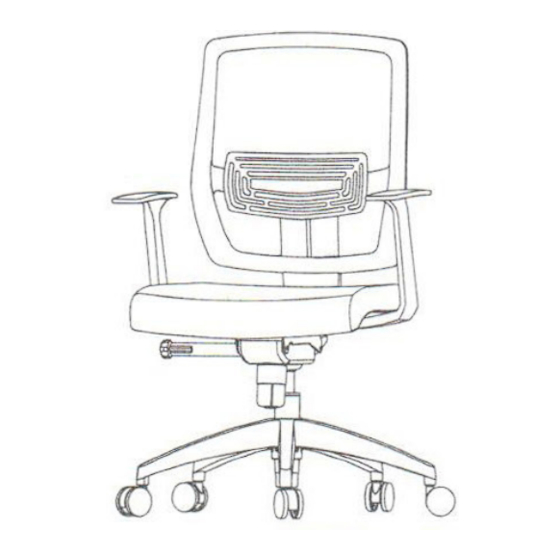
Aufbau
A Stecken Sie die Gasfeder mittig in das
Fußkreuz. Entfernen Sie (falls vorhanden)
vor dem Einbau die Schutzkappe vom Aus-
lösepin der Gasfeder. Diese lässt sich leicht
entfernen.
B Befestigen Sie die Mechanik am Sitzteil.
C Befestigen Sie die Armlehnen am Sitzteil
D Befestigen Sie die Rückenlehne am Sitzteil.
E Setzen Sie anschließend das Sitzteil auf die
Gasdruckfeder.
F Setzen Sie sich nun mehrmals auf den Stuhl,
damit die Verbindung zwischen Sitz, Gas-
feder und Fuß gefestigt wird. Anschließend
können Sie die Gasfeder bedienen und die
Stuhlhöhe individuell einstellen.
Sicherheitshinweis Gasfeder:
Gasfeder nie selbst zerlegen, einstechen oder
öffnen. Korpus steht unter Druck.
#
Bezeichnung
Stück
1
Rolle
5x
2
Fußkreuz
1x
3
Gasfeder
1x
4
Sitzfläche
1x
5
Rückenlehne
1x
6
Mechanik
1x
7
Armlehne
2x
8
Schraube M6x31,75
8x
9
Schraube M6x38
2x
10
Schraube M8x20
1x
11
Inbus
1x
Assembly
A Insert the five castors into designated holes
at the bottom of the 5-star base. Insert the
gaslift into the center of the base. If present,
remove the plastic protective cap from the
gas lift.
B Mount the mechanism onto the seat.
C Mount the arm rests onto the seat.
D Mount the back rest onto the seat.
E Place the seat onto the gaslift.
F Repeatedly sit onto the chair, so that the
connections between the seat, gaslift and
foot tighten. Now you can adjust the chair to
your individual needs.
Caution Gaslift:
Never disassemble, puncture or open Gas spring.
Gas cylinder is under pressure.
#
Part
Count
1
Castor
5x
2
Base
1x
3
Gaslift
1x
4
Seat
1x
5
Back rest
1x
6
Mechanism
1x
7
Arm rest
2x
8
Screw M6x31,75
8x
9
Screw M6x38
2x
10
Screw M8x20
1x
11
Allen wrench
1x
NET 90
Aufbauanleitung
Assembly instructions
AUFBAUVIDEO
FUNKTIONSVIDEO
Advertisement

Related Manuals for HJH office NET 90


Summary of Contents for HJH office NET 90
- Page 1 5-star base. Insert the vor dem Einbau die Schutzkappe vom Aus- gaslift into the center of the base. If present, NET 90 lösepin der Gasfeder. Diese lässt sich leicht remove the plastic protective cap from the entfernen.
- Page 2 Entfernen Sie (falls vorhanden) vor dem Einbau die Schutzkappe vom Auslösepin der Gasfeder. If present, remo- ve the plastic protective cap from the gas lift. Hinweis / Remark Packen Sie zunächst alle Teile der Lieferung aus und prüfen Sie diese auf eventuelle Transportschäden. Um einen leichten Aufbau zu gewährleisten, empfehlen wir alle Schrauben nur Siehe Rückseite für weitere Informationen.
Need help?
Do you have a question about the NET 90 and is the answer not in the manual?
Questions and answers