Advertisement
Quick Links
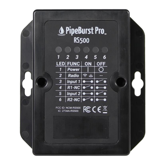
Basic Overview
The primary function of an RS500 Device is enabling wireless operation of equipment wired to it.
The RS Device operates as a control module for standard PipeBurst Pro 5 equipment including the
WaterValve and FloMeter.
RS500 Device Features
Dimensions
Power Source
Built-in Sensors
Voltage
Housing
Audible
Notification
Wireless
Frequency
Input 1 & 2
Options
Customer Support
GreenField Direct, LLC
th
14015 238
Street
Greenwood, NE 68366
www.pipeburstpro.com/contact
E-Mail: help@greenfielddirect.com
Phone: 866-466-LEAK (5325)
Hours of Operation: Weekdays 8:00 AM – 5:00 PM CT
RS500 Device User Manual
4-1/8" W x 4-3/4" H x 1-1/4" D
AC Power Adapter
Ambient Air Temperature Sensor
Tamper Alert Sensor
5 VDC
Black ABS Plastic
Internal Speaker
915 MHz
WaterValve
FloMeter
Warranty Information
PipeBurst Pro Products 2/5/7 Year Limited
Warranty
Please visit:
www.pipeburstpro.com/warranty
warranty details
Insert Device
Image
to review full
©2021 GreenField Direct, LLC
rev.4.15.2021
Advertisement

Summary of Contents for PipeBurst Pro RS500
- Page 1 RS500 Device User Manual Basic Overview The primary function of an RS500 Device is enabling wireless operation of equipment wired to it. The RS Device operates as a control module for standard PipeBurst Pro 5 equipment including the WaterValve and FloMeter.
- Page 2 1. On your ionleaks dashboard, go to the device tab and select add new device. 2. Enter in the device ID and device key for the RS500 and click add. Repeat this step for each sensor that needs to be added before proceeding to step 3.
- Page 3 RS500 Device Wiring Diagrams Function Power Power On Power Off Radio Radio Sleep transmitting Input 1 Input Closed Input Open Relay 1 (NC) Relay Open Relay Closed Input 2 Input Closed Input Open Relay 2 (NC) Relay Open Relay Closed...
- Page 4 RS Device Wiring Diagrams Key Components Relay button 5VDC Wire Terminals Wire Management Compartment...
- Page 5 RS Device Wiring Diagrams WaterValve - Control + Feedback IN 1 RLY 1 SIG: Green COM: Red GND: Black NC: White If using two WaterValves, repeat wiring for Input 2 / Relay 2...
- Page 6 RS Device Wiring Diagrams FloMeter IN 2 SIG: Green GND: Black If using two FloMeters, repeat wiring for Input 1...
- Page 7 RS500 FCC-ISED Declaration FCC § 15.19 Labelling requirements This device complies with part 15 of the FCC Rules and Innovation, Science and Economic Development Canada (ISED) license- exempt RSS standard(s). Operation is subject to the following two conditions: (1) This device may not cause harmful interference, and (2) this device must accept any interference received, including interference that may cause undesired operation.
Need help?
Do you have a question about the RS500 and is the answer not in the manual?
Questions and answers