Table of Contents
Advertisement
Quick Links
Advertisement
Table of Contents

Related Manuals for Expert Sleepers Aloysius


Summary of Contents for Expert Sleepers Aloysius
- Page 1 Aloysius User Manual Revision 1.0...
- Page 2 Expert Sleepers Ltd. Expert Sleepers Ltd assumes no responsibility or liability for any errors or inaccuracies that may appear in this document.
-
Page 3: Table Of Contents
Table of Contents Introduction..................................4 Installation.................................... 4 Power requirements..............................4 Inputs and outputs................................5 Controls....................................5 Theory of operation................................ 5 'Hold' mode..................................5 'Gated' mode.................................. 6 'Auto' mode..................................7 Time ranges..................................7 Envelope shapes................................7 Calibration.................................... 8 Hacking resources................................9 Where to get help................................ -
Page 4: Introduction
Be sure to connect the other end of the power cable correctly, again so -12V corresponds to the red stripe on the cable. Power requirements Aloysius draws up to 43mA on the +12V rail, and 25mA on the -12V rail. It does not use the 5V rail. 1 http://www.doepfer.de/a100_man/a100t_e.htm... -
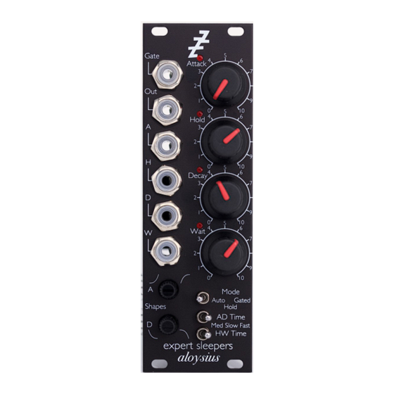
Page 5: Inputs And Outputs
Inputs and outputs Aloysius's input and output jack sockets are illuminated, lighting red for positive voltage and blue for negative voltage. (Audio appears purple, since it is a rapid alternation of positive and negative.) From top to bottom, Aloysius's sockets are: Gate/trigger input –... -
Page 6: Gated' Mode
Hold mode The envelope always rises to the maximum level, even if the trigger is shorter than the time it takes to do so. The envelope can be retriggered during the decay stage, in which case it begins to rise again to the maximum level. -
Page 7: Auto' Mode
Gated mode – gate shorter than attack Gated mode – gate longer than attack 'Auto' mode In this mode, the envelope becomes a free-running LFO. When the level hits 0V at the end of the decay stage, the envelope waits for the time set by the Wait knob (and CV) before automatically retriggering the attack. -
Page 8: Calibration
Exponential attack Logarithmic attack The lower knob (marked 'D') sets the shape of the decay stage, in a similar manner. Exponential decay Logarithmic decay Note that a traditional analogue ADSR envelope generator has a logarithmic attack and an exponential decay/release. Logarithmic attack, exponential decay Calibration There are two trimmer pots on the upper PCB. -
Page 9: Hacking Resources
envelope time knobs to maximum and measuring the voltage at test point TP3. The factory setting is 10mV. If, at high values of Attack/Decay and extreme values of the shape knobs, the envelope doesn't progress as expected – for example, if the envelope gets stuck in Attack and never moves on to Hold –...
Need help?
Do you have a question about the Aloysius and is the answer not in the manual?
Questions and answers