
Subscribe to Our Youtube Channel
Summary of Contents for Conductix-Wampfler MPU 3.0
- Page 1 Technical Description MPU 3.0 Mobile Power Unit Item number 3267229 CWA-60691000 TNB_0085_MPU30 www.conductix.com...
- Page 2 Conductix-Wampfler Automation GmbH Handelshof 16 A 14478 Potsdam Germany Telephone: +49 (0)331 887433-0 Fax: +49 (0)331 887433-19 Email: info.potsdam@conductix.com Internet: www.conductix.com Translation of the original TNB_0085, 2, en_GB © 2023 Conductix-Wampfler Automation GmbH...
-
Page 3: Table Of Contents
Charging process - controlled by BMS and PLC......25 4.4.4 Charging process - controlled by PLC......... 26 4.4.5 Charging process - controlled by AGV controller......27 Enable commands for charging process........28 Inductive communication............. 29 MPU 3.0 Conductix-Wampfler Automation GmbH / 01/2023... - Page 4 Charging process................ 53 10.4.1 Automatic adjustment of the primary current....... 53 10.4.2 Temperature generation during the charging process....53 10.4.3 Power reduction with temperature increase........ 54 10.4.4 Power reduction in case of pad displacement......55 MPU 3.0 Conductix-Wampfler Automation GmbH / 01/2023...
- Page 5 Cooling..................67 14.5 Environmental conditions............68 14.6 Input data..................69 14.7 Output data.................. 69 14.8 Cable lengths and specifications..........70 14.9 Approvals and standards............. 72 Customer service and addresses............73 Index......................75 Appendix....................77 MPU 3.0 Conductix-Wampfler Automation GmbH / 01/2023...
- Page 6 Table of contents MPU 3.0 Conductix-Wampfler Automation GmbH / 01/2023...
-
Page 7: Information On The Description
IPS 3.0 TNB_0083_IPS30 Inductive Power Supply ISP 3.0 Inductive Stationary Pad TNB_0073_ISP30_IMP30 IMP 3.0 Inductive Mobile Pad MPU 3.0 TNB_0085_MPU30 Mobile Power Unit Software Related description Wireless Charger 3.0 SWB_0021_Wireless-Charger-Web-Interface_User_Admin Web Interface MPU 3.0 Conductix-Wampfler Automation GmbH / 01/2023... -
Page 8: Copyright Protection
No claims shall be accepted for possible discrepancies. Brands The popular names, trade names, production descriptions, etc. used in this description may constitute trademarks even without special designations and as such may be subject to legal requirements. MPU 3.0 Conductix-Wampfler Automation GmbH / 01/2023... -
Page 9: Warranty And Liability
All information and notes in this description have been compiled taking into account the applicable standards and regulations, the state of the art and our many years of knowledge and experience. Conductix-Wampfler Automation GmbH assumes no liability for damage and malfunctions during operation due to: Failure to comply with the description... -
Page 10: Safety Instructions
Only then can safe operation be guaranteed. Of course, all legally applicable general safety and accident prevention reg- ulations must be complied with. Conductix-Wampfler Automation GmbH assumes no liability for damage or accidents that were caused by non-observance of these safety notes. Warning concept This description contains notes that must be observed for your own per- sonal safety and to avoid property damage. -
Page 11: Signal Words
Warning signs Type of danger Warning – high-voltage. Warning – non-ionising electromag- netic radiation. Warning – danger zone. 3.1.5 Suggestions and recommendations This symbol indicates important information to help you handle the product. MPU 3.0 Conductix-Wampfler Automation GmbH / 01/2023... -
Page 12: Intended Use
Intended use The device has been designed and constructed exclusively for the intended use described below. The mobile power supply MPU 3.0 (Mobile Power Unit) is a device designed for use in commercial and industrial transport sys- tems. is part of the ‘Wireless Charger 3.0’ inductive charging system for charging batteries in AGVs. -
Page 13: Modifications And Alterations
Automation GmbH's express consent. L WARNING! Injury hazard from structural modifications! Unauthorised technical modifications can cause bodily harm or material damage. Replace faulty devices. A faulty device should only be replaced by an identical device. MPU 3.0 Conductix-Wampfler Automation GmbH / 01/2023... -
Page 14: Responsibility Of The Operator
Due to their training and experience, qualified personnel are able to recog- nize risks and avoid possible hazards when dealing with this product / system. MPU 3.0 Conductix-Wampfler Automation GmbH / 01/2023... - Page 15 Whenever working on the device, disconnect it from the power supply and secure it against being switched on again. Prior to commissioning, make sure that all safety equipment is installed and functioning properly. MPU 3.0 Conductix-Wampfler Automation GmbH / 01/2023...
- Page 16 Improper handling can cause substantial bodily harm or material damage. Only allow the device to be operated and maintained by trained and instructed personnel. Only have work on electrical components carried out by a qualified electrician. MPU 3.0 Conductix-Wampfler Automation GmbH / 01/2023...
-
Page 17: Special Hazards
L WARNING! Electromagnetic fields Death or serious injuries Electromagnetic fields can affect and interfere with pacemakers and defibrillators. If you carry a pacemaker, keep sufficient distance. Warn people wearing pacemakers before they get close. MPU 3.0 Conductix-Wampfler Automation GmbH / 01/2023... -
Page 18: Safety Devices
Safety instructions Safety devices Safety devices L WARNING! Danger to life from non-functioning safety devices! Check the safety devices before starting work. Report faulty safety equipment. Have faulty safety equipment repaired. MPU 3.0 Conductix-Wampfler Automation GmbH / 01/2023... -
Page 19: Wireless Charger Wc 3.0 - System Overview
IPS 3.0 - Inductive Power Supply Stationary charging pad ISP 3.0 - Inductive Stationary Pad Mobile components: Mobile charging pad ISP 3.0 - Inductive Mobile Pad Mobile power supply MPU 3.0 - Mobile Power Unit MPU 3.0 Conductix-Wampfler Automation GmbH / 01/2023... -
Page 20: How It Works
The pads cannot detect their position in relation to each other. Only the quality of the data signal is evaluated. The charging process can only be started if the signal is sufficiently stable. Optimal positioning must be achieved by using suitable external equip- ment. MPU 3.0 Conductix-Wampfler Automation GmbH / 01/2023... -
Page 21: Control Circuit
The MPU adjusts the demand from all external requests along with the measurands, such as voltage, current, temperature. Controlling the charging process The charging process is controlled according to 2 methods: Continuous charging Controlled charging MPU 3.0 Conductix-Wampfler Automation GmbH / 01/2023... - Page 22 Automatic modes PLC managed modes non-communi- for batteries with BMS-based AGV controller- AGV controller- cating batteries & CAN communica- charging adapted based charging based charging demos tion by the PLC Batteries without communication MPU 3.0 Conductix-Wampfler Automation GmbH / 01/2023...
-
Page 23: Charging Process - Continuous
Charging Mode: Continuous Fig. 3 1 IPS - Inductive Power Supply 2 ISP - Inductive Stationary Pad 3 IMP - Inductive Mobile Pad (AGV) 4 MPU - Mobile Power Unit (AGV) 5 Battery (AGV) MPU 3.0 Conductix-Wampfler Automation GmbH / 01/2023... -
Page 24: Charging Process - Controlled By Bms Controller
1 IPS - Inductive Power Supply 2 ISP - Inductive Stationary Pad 3 IMP - Inductive Mobile Pad (AGV) 4 MPU - Mobile Power Unit (AGV) 5 Battery management (AGV) 6 Battery (AGV) 7 PLC MPU 3.0 Conductix-Wampfler Automation GmbH / 01/2023... -
Page 25: Charging Process - Controlled By Bms And Plc
2 ISP - Inductive Stationary Pad 3 IMP - Inductive Mobile Pad (AGV) 4 MPU - Mobile Power Unit (AGV) 5 Battery management (AGV) 6 Battery (AGV) 7 Vehicle control (AGV) 8 PLC MPU 3.0 Conductix-Wampfler Automation GmbH / 01/2023... -
Page 26: Charging Process - Controlled By Plc
1 IPS - Inductive Power Supply 2 ISP - Inductive Stationary Pad 3 IMP - Inductive Mobile Pad (AGV) 4 MPU - Mobile Power Unit (AGV) 5 Battery (AGV) 6 Vehicle control (AGV) 7 PLC MPU 3.0 Conductix-Wampfler Automation GmbH / 01/2023... -
Page 27: Charging Process - Controlled By Agv Controller
1 IPS - Inductive Power Supply 2 ISP - Inductive Stationary Pad 3 IMP - Inductive Mobile Pad (AGV) 4 MPU - Mobile Power Unit (AGV) 5 Battery (AGV) 6 Vehicle control (AGV) 7 PLC MPU 3.0 Conductix-Wampfler Automation GmbH / 01/2023... -
Page 28: Enable Commands For Charging Process
It is possible to combine the start of the charging process at the IPS with defined enable commands. Depending on the parametrisation, these can be limit switches or similar items or else enable commands from the system controller via Ethernet. Start Fig. 8 MPU 3.0 Conductix-Wampfler Automation GmbH / 01/2023... -
Page 29: Inductive Communication
Stationary Pad Fig. 9: Inductive communication 1 Inductive Power Supply 2 Inductive Stationary Pad 3 Inductive Mobile Pad (AGV) 4 Mobile Power Unit (AGV) 5 Battery management (AGV) 6 Vehicle control (AGV) 7 PLC MPU 3.0 Conductix-Wampfler Automation GmbH / 01/2023... -
Page 30: Product Description
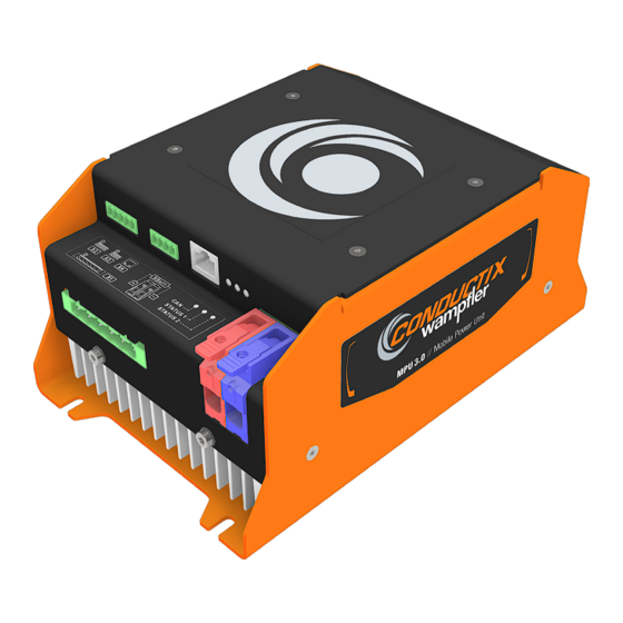
Product description Function Product description Structure Fig. 10: MPU 3.0 1 Housing 2 LED status indicators 3 Battery connections 4 Electrical connections 5 Heat sink Function The MPU (Mobile Power Unit) converts the induced alternating current from the IMP (Inductive Mobile Pad) into a battery charging current. -
Page 31: Type Label
MPU 3.0 - Name Item Scope of delivery Numbe Scope of number delivery MPU 3.0 3267229 CWA-60691000 Basic device MPU 3.0 Mobile Power CAN connector: Unit Phoenix circuit board con- nector, 4-pin MC 1.5/ 4-ST-3.81f 5.4.2 Product sets WCS 3.0 - Name... - Page 32 Scope of delivery > Product sets WCM 3.0 - Name Item Scope of delivery Numbe Scope of number delivery WCM 3.0 Set 3276340 CWA-60690000 MPU 3.0 Mobile Power Unit Wireless Charger Mobile IMP 3.0 Inductive Mobile Pad MPU 3.0 Conductix-Wampfler Automation GmbH / 01/2023...
-
Page 33: Transport And Storage
Initiate a complaints process and report the incident to the supplier. If Conductix-Wampfler Automation is your direct supplier you will find our contact information in this document. Ä Chapter ‘Customer service and addresses’ on page 73 Claims for damages Claim any defect as soon as it becomes apparent. -
Page 34: Storage
Store in a dry and dust-free location. Regularly check the condition of the stored device. Keep environmental conditions as specified in the technical informa- tion. Keep the storage temperature as specified in the technical informa- tion. MPU 3.0 Conductix-Wampfler Automation GmbH / 01/2023... -
Page 35: Mechanical Installation
Safety shoes Protective gloves Protective goggles Safety in the Note the safety signs in the area around the system. work area Pay attention to the safety notes in additional applicable documentation (supplier documents). MPU 3.0 Conductix-Wampfler Automation GmbH / 01/2023... - Page 36 Disconnect the power supply of the device before mechanically and electrically installing the device. Take the necessary measures to ensure that the power supply of the device cannot be switched on again unintentionally. MPU 3.0 Conductix-Wampfler Automation GmbH / 01/2023...
-
Page 37: Installation Location And Position
AGV). Installation The MPU can be installed in horizontal and vertical position. position Fig. 12: MPU 3.0 installation position The following factors should be considered for the assembly location: Ä Chapter ‘Open spaces and cooling’ Sufficient air circulation ( on page 38) -
Page 38: Open Spaces And Cooling
Passive cooling under high load is sufficient if: The device is installed in a vertical installation position. Air can circulate without restrictions. Ambient temperature does not exceed 30 °C. No external heat source in the immediate vicinity. MPU 3.0 Conductix-Wampfler Automation GmbH / 01/2023... - Page 39 If the temperature continues to rise despite reduced charging current, the charging process is aborted and a fault message is dis- played. MPU 3.0 Conductix-Wampfler Automation GmbH / 01/2023...
-
Page 40: Installation
Use vibration-damping and vibration-eliminating systems. Fixing points The mobile power unit must be fitted at the fixing points provided. 100 mm 204 mm Fig. 15: MPU 3.0 fixing points Data Value Unit Hole distance (x) 100 mm Hole distance (y) 204 mm Hole Æ... -
Page 41: Electrical Installation
Safety shoes Protective gloves Protective goggles Safety in the Note the safety signs in the area around the system. work area Pay attention to the safety notes in additional applicable documentation (supplier documents). MPU 3.0 Conductix-Wampfler Automation GmbH / 01/2023... - Page 42 Disconnect the power supply of the device before mechanically and electrically installing the device. Take the necessary measures to ensure that the power supply of the device cannot be switched on again unintentionally. MPU 3.0 Conductix-Wampfler Automation GmbH / 01/2023...
-
Page 43: Electrical Connections
Electrical installation Electrical connections > Pin configuration Electrical connections 8.1.1 Connection overview XBatt+ XBatt− Fig. 16: MPU 3.0 connections Connection Designation Connect to: IMP Power Inductive Mobile Pad - Power IMP Signal Inductive Mobile Pad - Data CAN bus/fan CAN bus / fan (optional) Ethernet External Ethernet device, e.g. -
Page 44: X1 - Imp-Power
Phoenix SH (shielding) MC 1.5/ 5-G-3.81 Temp 8.1.2.3 X3 - CAN bus/fan X3 pin assignment CAN bus/fan Connection type Connection image Signal CAN_L CAN_H Phoenix MC 1.5/ 4-G-3.81 Connector Phoenix MC 1.5/4-ST-3.81 (included) MPU 3.0 Conductix-Wampfler Automation GmbH / 01/2023... -
Page 45: X4 - Ethernet
XBatt+ / XBatt- pin assignment Battery Connection type Connection image Terminal Signal XBatt+ (red) Battery plus max. 16 mm Phoenix XBatt- (blue) Battery minus LPT 16/ 1-10 RD max. 16 mm (red) LPT 16/ 1-10 BU (blue) MPU 3.0 Conductix-Wampfler Automation GmbH / 01/2023... -
Page 46: Floor Conductivity
Ferromagnetic components in the coating The electrically conductive coating must not contain any ferromagnetic components in the immediate vicinity of the pads. Possible influence on the inductive system. Possible damage due to intense heating. MPU 3.0 Conductix-Wampfler Automation GmbH / 01/2023... -
Page 47: Commissioning
Fig. 17: Wireless Charger - Software Reference For information about the wireless charger web interface, please refer to the corresponding description: SWB_0021_Wireless-Charger-Web-Interface The description is part of the project documentation and can be down- loaded from www.conductix.com. MPU 3.0 Conductix-Wampfler Automation GmbH / 01/2023... -
Page 48: Operation
Only work when protection and monitoring equipment are active. work area Pay attention to the safety signs at the work station and its immediate vicinity. Only load load-bearing machinery within the permitted limits. Secure goods to be transported against loss. MPU 3.0 Conductix-Wampfler Automation GmbH / 01/2023... - Page 49 Special haz- ards L WARNING! Hazardous voltages on ports and cables Open electrical components Do not pull plugs carrying voltage. Do not contact open cables. MPU 3.0 Conductix-Wampfler Automation GmbH / 01/2023...
-
Page 50: Switching The Device On And Off
The status LEDs indicate the system status of the MPU. They can display different colours and flashing modes. The status LED check is intended for commissioning and maintenance work (troubleshooting). Fig. 18: Status LEDs 1 CAN status indicator 2 Operation indicator 3 Fault indicator MPU 3.0 Conductix-Wampfler Automation GmbH / 01/2023... - Page 51 Charging process active Status 2 No warning Faults No fault Initialisation succeeded Warning is pending Yellow Flashes Fault during configuration No firmware Amber Flashes Bootloader starts Fault in operation Flashes Fault during initialisation MPU 3.0 Conductix-Wampfler Automation GmbH / 01/2023...
-
Page 52: Operating Modes
(BMS or AGV controller) upstream of the MPU and controlled by commands to the MPU. Charging process controlled by: Battery management system and system controller Battery management system only System controller only AGV controller or similar only MPU 3.0 Conductix-Wampfler Automation GmbH / 01/2023... -
Page 53: Charging Process
A fault message is output. MPU tempera- Data Value Unit ture control Warning message 85 °C 4 High temperature at heat sink 4 Charging current will be reduced Ä ‘W326’ on page 58 MPU 3.0 Conductix-Wampfler Automation GmbH / 01/2023... -
Page 54: Power Reduction With Temperature Increase
Power reduction with temperature increase Derating During the charging process, all connected components heat up. The heating depends on the operating time, the transmitted power, the charging current and the installation conditions (possibility of heat dissipation). MPU 3.0 Conductix-Wampfler Automation GmbH / 01/2023... -
Page 55: Power Reduction In Case Of Pad Displacement
If the pads are aligned with each other within the maximum deviation (working range), the continuous power transmission is guaranteed. Deviations from the working range lead to power losses and can cause system failures. MPU 3.0 Conductix-Wampfler Automation GmbH / 01/2023... -
Page 56: Faults
RTC battery low voltage Ä ‘F317’ on page 62 F317 Parameter read/write error Ä ‘F318’ on page 62 F318 Firmware error logging Ä ‘F319’ on page 63 F319 Parameter value out of range MPU 3.0 Conductix-Wampfler Automation GmbH / 01/2023... - Page 57 Faults MPU faults Ä ‘F320’ on page 63 F320 CAN communication disrupted Ä ‘F321’ on page 63 F321 Intermediate circuit excess voltage MPU 3.0 Conductix-Wampfler Automation GmbH / 01/2023...
-
Page 58: Warning Indicators
The output power at the IPS is reduced until it falls below the set threshold value again. Error F314 appears if the temperature continues to rise. Ä ‘F314’ on page 61 Solution If the value falls below the set threshold again, the warning resets automatically. MPU 3.0 Conductix-Wampfler Automation GmbH / 01/2023... - Page 59 Effect None If the battery voltage continues to drop, error F316 is issued. Ä ‘F316’ on page 62 Solution If the value falls below the set threshold again, the warning resets automatically. MPU 3.0 Conductix-Wampfler Automation GmbH / 01/2023...
-
Page 60: Fault Indicators
Passive cooling disrupted Function of the fan disrupted Ambient temperature is too high Effect Power transmission will be aborted Solution "Error must be reset via the interface. Temperature must be below the lower limits" MPU 3.0 Conductix-Wampfler Automation GmbH / 01/2023... - Page 61 Charging- PAD Temperature Err Description Pad excess temperature according to software setpoint Cause Passive cooling disrupted Ambient temperature is too high Effect Power transmission will be aborted Solution Self-resetting after falling below threshold value MPU 3.0 Conductix-Wampfler Automation GmbH / 01/2023...
- Page 62 F318 MPU - Mobile Power Unit Fault F318 Display text Firmware error logging Status 2 Red/steady light Code MRAM Read/Write Err Description Firmware error/logging error Effect No system start possible. Solution Customer support MPU 3.0 Conductix-Wampfler Automation GmbH / 01/2023...
- Page 63 Display text Intermediate circuit excess voltage Status 2 Red/flashing Code Over Voltage Err Description Overvoltage detected in the intermediate circuit. Effect Charging process stops Solution The error is reset after a system restart. MPU 3.0 Conductix-Wampfler Automation GmbH / 01/2023...
-
Page 64: Maintenance And Cleaning
Brackets Check for loose connections. Connections Check for loose connections. Check cable insulation. Cover any ports not being used. Indicators Remove soiling. Recommended maintenance interval 6 months MPU 3.0 Conductix-Wampfler Automation GmbH / 01/2023... -
Page 65: Cleaning
Do not use any cleaning agents, such as methylated spirits, or other cleaners! Do not clean with sharp objects! Clean the device as follows: Device Clean with dry cloths only. Recommended cleaning intervals 6 months MPU 3.0 Conductix-Wampfler Automation GmbH / 01/2023... -
Page 66: Information On Disposal And Environmental Regulations
Follow the hazardous materials directive, in particular the regulations on handling hazardous materials. Materials designated for recycling are to be disposed of as per the respective recycling procedure. MPU 3.0 Conductix-Wampfler Automation GmbH / 01/2023... -
Page 67: Technical Data
Value Unit Weight 2800 g 14.3 Material Material Data Value Housing cover Aluminium Housing main body Aluminium Housing heat sink Aluminium 14.4 Cooling Data Value Cooling Passive con- vection Fan-assisted cooling Active convec- tion MPU 3.0 Conductix-Wampfler Automation GmbH / 01/2023... -
Page 68: Environmental Conditions
DIN IEC 60068-2-27 Shocks during operation 50 m/s DIN IEC 60068-2-27 Oscillation, broadband noise with tempera- 5.72 m/s ture change 100 ... 150 Hz DIN IEC 60068-2-53 Impact 1 Nm DIN IEC 60068-2-75:1997 MPU 3.0 Conductix-Wampfler Automation GmbH / 01/2023... -
Page 69: Input Data
Derating to 51 A at 59 V Continuous output power 3 kW Maximum output power 3 kW Data Value Unit X3 fan output - voltage 12 V DC X3 fan output - current 200 mA MPU 3.0 Conductix-Wampfler Automation GmbH / 01/2023... -
Page 70: Cable Lengths And Specifications
Signal cable, shielded 10 m according to DIN VDE/UL or other national standards Fig. 21/6 IPS/X6 ISP data Data cable (permanently installed on 10 m ISP) Unitronic FD Li2YCY (TP) A BE 2x2x0.34 MPU 3.0 Conductix-Wampfler Automation GmbH / 01/2023... - Page 71 , twisted in pairs, shielded Fig. 21/9 MPU/X4 Ethernet Data cable min. CAT5e Fig. 21/10 MPU/XBatt+ Battery plus Battery cable max. 1x16 mm Fig. 21/11 MPU/XBatt- Battery minus Battery cable max. 1 x 16 mm MPU 3.0 Conductix-Wampfler Automation GmbH / 01/2023...
-
Page 72: Approvals And Standards
14.9 Approvals and standards Conformity Devices made by Conductix-Wampfler Automation GmbH have been designed to comply with EU directives. Please contact Conductix-Wampfler Automation GmbH if you wish to obtain a copy of the EU Declaration of Conformity. Standards The devices and the entire system are tested according to the following... -
Page 73: Customer Service And Addresses
Rheinstrasse 27 + 33 | 79576 Weil am Rhein | Germany Phone: +49 7621 662-0 | Fax: +49 7621 662-144 E-mail: info.de@conductix.com | Internet: www.conductix.com For further addresses of sales and service locations, visit: www.conductix.com MPU 3.0 Conductix-Wampfler Automation GmbH / 01/2023... - Page 74 Customer service and addresses MPU 3.0 Conductix-Wampfler Automation GmbH / 01/2023...
-
Page 75: Index
F318............. 56, 62 Storage............34 F319............. 56, 63 F320............. 56, 63 Transport............ 33 F321............. 56, 63 Type label........... 31 Inductive communication......29 W325............ 56, 58 W326............ 56, 58 W327............ 56, 59 Warranty............9 MPU 3.0 Conductix-Wampfler Automation GmbH / 01/2023... - Page 76 Index MPU 3.0 Conductix-Wampfler Automation GmbH / 01/2023...
-
Page 77: Appendix
Appendix Appendix MPU 3.0 Conductix-Wampfler Automation GmbH / 01/2023... - Page 78 Appendix MPU 3.0 Conductix-Wampfler Automation GmbH / 01/2023...
- Page 79 Appendix MPU 3.0 Conductix-Wampfler Automation GmbH / 01/2023...
- Page 80 Appendix MPU 3.0 Conductix-Wampfler Automation GmbH / 01/2023...
- Page 81 Appendix MPU 3.0 Conductix-Wampfler Automation GmbH / 01/2023...
Need help?
Do you have a question about the MPU 3.0 and is the answer not in the manual?
Questions and answers