Advertisement
Quick Links
UNVENTED MAINS PRESSURE WATER HEATER
WITH FTC6 CONTROL SYSTEM. FOR USE WITH
ECODAN PUZ-(H)WM AIR SOURCE HEAT PUMP
RANGE.
Installation, Operation, Service & Parts Manual
EHPT18X-UKHLDWB
EHPT21X-UKHLDWB
EHPT21X-UKHDWB
EHPT25X-UKHDWB
EHPT30X-UKHDWB
IMPORTANT: PLEASE READ AND UNDERSTAND THESE INSTRUCTIONS
BEFORE COMMENCING INSTALLATION , OPERATING THE UNIT OR
PLEASE LEAVE THIS MANUAL WITH THE CUSTOMER FOR FUTURE REFERENCE.
PERFORMING ANY MAINTENANCE.
Renewable Heating Technology
July 2023
Doc. No. 685702
EDITION-1
Advertisement

Summary of Contents for Ecodan EHPT18X-UKHLDWB
- Page 1 Renewable Heating Technology UNVENTED MAINS PRESSURE WATER HEATER July 2023 WITH FTC6 CONTROL SYSTEM. FOR USE WITH ECODAN PUZ-(H)WM AIR SOURCE HEAT PUMP Doc. No. 685702 RANGE. EDITION-1 Installation, Operation, Service & Parts Manual EHPT18X-UKHLDWB EHPT21X-UKHLDWB EHPT21X-UKHDWB EHPT25X-UKHDWB EHPT30X-UKHDWB IMPORTANT: PLEASE READ AND UNDERSTAND THESE INSTRUCTIONS BEFORE COMMENCING INSTALLATION , OPERATING THE UNIT OR PERFORMING ANY MAINTENANCE.
-
Page 2: Table Of Contents
Contents Abbreviations and Glossary Safety Precautions Introduction Specification Details Product Diagrams Fiche Performance Data Preparing to Install the Cylinder Installation Instructions Wiring Diagram Electrical Work System Set Up Operator and owner info Commissioning Servicing Annual Maintenance Log Book Servicing Troubleshooting Test Plot Diagram Disassembly / Decommissioning Procedure Service &... - Page 3 Safety Precaution Please read the following safety precautions carefully. WARNING: CAUTION: Precautions that must be observed to prevent injuries or death. Precautions that must be observed to prevent damage to unit. • Be sure to perform periodical maintenance. • Be sure to follow your local regulations. •...
- Page 4 CAUTION Use clean water that meets local quality standards on the primary circuit. The outdoor unit should be installed in an area with sufficient airflow according to the diagrams in the outdoor units installation manual. The cylinder unit should be located inside to minimise heat loss. Water pipe-runs on the primary circuit between outdoor and indoor unit should be kept to a minimum to reduce heat loss.
- Page 5 Important Note: Included with the Ecodan product is information about how to register the Mitsubishi Electric user guarantee. Please direct the end user to register within 3 months of commissioning to ensure they benefit from the applicable standard guarantee for their Ecodan heat pump and any cylinder or interfacing equipment purchased from Mitsubishi Electric by you as installer.
- Page 6 Specification Details The unvented cylinders are made from Duplex stainless steel Coil Presure Drop for corrosion resistance, are encased in a strong rust-proofed Slimline Cylinders steel case and are highly insulated with environmentally- friendly foam. Further details are below. Materials •...
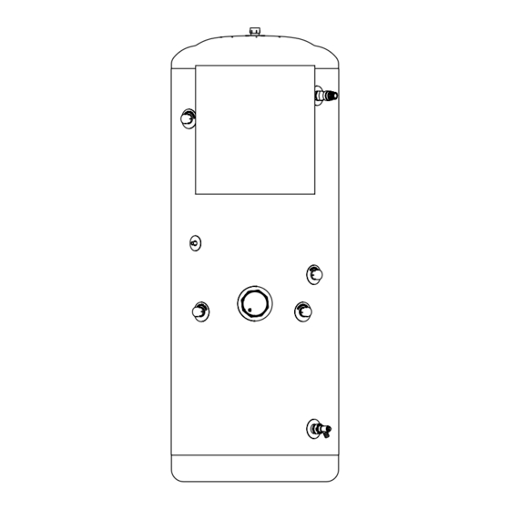
- Page 7 D Heat pump coil connections - 22mm / ¾" BSP E 7 Bar 90°C Temperature & pressure relief valve - ½”NPT x 15mm F Secondary return - 22mm / ¾" BSP (Excluding EHPT18X-UKHLDWB) G Dry stat pocket - 10mm (with thermostat probe fitted) H Drain cock...
- Page 8 Outlets above the unvented cylinder will reduce the outlet pressure available by 0.1 bar for every 1m of height difference. EHPT18X-UKHLDWB 1832 The unvented cylinder must be installed indoors in a frost-free environment and all exposed pipework should be insulated.
- Page 9 Ecodan heat pumps also require anti-freeze protection. immersion heater to be replaced at the end of its working life Failure to do so will put the product Warranty at risk.
- Page 10 Ecodan R32 heat pumps include an integral 3 bar PRV. No additional PRV’s should be added to the circuit. Heat Pump to Cylinder Compatibility...
- Page 11 Installation Instructions - Unvented Cylinders Immersion Heater Wiring Minimum required water volume and required Immersion Heater Wiring primary flow rates Min. water Required Outdoor heat pump unit flow rate volume PUZ-WM50VHA 14.3L/min PUZ-WM60VAA 17.2L/min PUZ-WM85(V-Y)AA 24.4L/min PUZ-WM112(V-Y)AA 32.1L/min PUZ-HWM140(V-Y)HA 40.1L/min If the interlock operation of primary and secondary pump is not available, ensure required additional water in only primary CN108...
- Page 12 Installation Instructions - Unvented Cylinders (cont.) System Schematic System Schematic Main Wi-Fi FIC6 Board Immersion Controller Adaptor 230V|SP+N|50Hz 230V|SP+N|50Hz Main 12V DC Controller (2 x 0.3mm FTC6 SECONDARY RETURN CIRCUIT (210, 250 & 300L SIZES) Flow to heating system Zone 1 Heating Rads/UFH/FC Return from heating system DRAIN...
- Page 13 Installation Instructions - Unvented Cylinders (cont.) Key: Items supplied with cylinder To hot water outlets Pressure Pressure Check Inline To cold water outlets relief valve reducing valve valve strainer 1 x Cold water combination valve Cold water combination BALANCED POTABLE valve COLD WATER...
- Page 14 Installation Instructions - Unvented Cylinders (cont.) must be taken into account in calculating the flow resistance. Discharge arrangement Refer to the diagram, Table 2 and the worked example. You will need to position the inlet control group so that the An alternative approach for sizing discharge pipes would be discharge from both safety valves can be joined together via to follow BS EN 806:2 specifications for design, installation,...
- Page 15 Wiring Diagram...
- Page 16 Electrical Work All electrical work should be carried out by a suitably qualified technician. Failure to comply with this could lead to electrocution, fire and death. It will also invalidate product guarantee. All wiring should be according to national wiring regulations.
- Page 17 Electrical Work Connecting inputs/outputs TBO.1 CN01 ( BK) Signal inputs CNP1 ( WH) CN3C Name Terminal block Connector Item OFF (Open) ON (Short) CNP4 ( BU) TBO.2 ( RD) LED1 TBI.1 7-8 — Room thermostat 1 input *1 Refer to SW2-1 CNPWM ( WH) TBI.1 5-6...
- Page 18 Electrical Work inputs Name Terminal block Connector Item OFF (Open) Ensure to wire thermistor wirings away from the — CN20 Thermistor (Room temp.) (Option) *1 PAC-SE41TS-E power line and/or OUT1 to 16 wirings. — CN21 Thermistor (Ref. liquid temp.) *2 —...
- Page 19 System Set Up DIP Switch Functions Located on the FTC printed circuit board are 6 sets of small white switches known as DIP switches. The DIP switch number is printed on the circuit board next to the relevant switches. The word ON is printed on the circuit board and on the DIP switch block itself.
- Page 20 The cylinder units are supplied fitted with a Wi-Fi adapter which can on the FTC control board are all off. be used to easily pair your Ecodan system to the internet to enable 6. The read and write operations have been verified using the remote control, monitoring, maintenance and technical support.
-
Page 21: Compensation Curve Mode
System Set Up <Main remote controller parts> Main remote controller Letter Name Function To change the settings of your heating/cooling system, please use the main Screen Screen in which all information is displayed. remote controller. The following is a guide to viewing the main settings. Should Menu Access to system settings for initial set up and modifications. - Page 22 System Set Up Setting the main remote controller After the power has been connected to the outdoor and cylinder units, the initial system settings can be entered via the main remote controller. 1. Check all breakers and other safety devices are correctly installed and turn on power to the system. 2.
-
Page 23: Dhw Mode
System Set Up <Main Remote Controller Menu Tree> Initial Unrestricted access Installer only Main screen * Short press for 1 Zone system. Long press Information Option ON ( )/OFF Forced DHW ON ( )/Prohibited ( )/Timer ( ) ON ( )/Prohibited ( )/Timer ( ) Heating/Cooling Energy monitor Consumed electrical energy... -
Page 24: Freeze Stat Function
System Set Up <Continued from the previous page.> <Main Controller Menu Tree> Unrestricted access Initial Installer only Main screen Main Long press menu Manual operation Menu Function settings Service Thermistor adjustment Password protected ON/OFF Economy settings for pump Delay ON/OFF Electric heater (Heating) Delay ON/OFF (Booster heater/Immersion heater) -
Page 25: Ftc
System Set Up <Continued from the previous page.> <Main Controller Menu Tree> Unrestricted access Initial Installer only Main screen Main menu Long press Menu Booster heater 1 capacity Electric heater Booster heater 2 capacity capacity Immersion heater Analog output Pump 1 Energy monitor Water pump input Pump 2... -
Page 26: Legionella
System Set Up Legionella Prevention Mode settings Please note that LP mode uses the assistance of electric heaters (LP mode) to supplement the energy input of the heat pump. Heating water for long periods of time is not efficient and will increase running 1. - Page 27 The system automatically stops 2 hours after the last operation. <Operation settings> Heating operation This function allows operational setting of flow temperature range from the Ecodan and also the time interval at which the FTC collects and processes data for the auto adaptation mode. Menu subtitle...
- Page 28 System Set Up Target flow temp. <Floor dry up function> (°C ) The Floor dry up function automatically changes the target hot water temperature in stages to gradually dry concrete when this particular type of underfloor heating system is installed. Upon completion of the operation the system stops all the operations except the Freeze stat.
- Page 29 System Set Up <Energy monitor settings> In this menu, all parameters required to record the consumed electrical energy and the delivered heat energy which is displayed on the main remote controller can be set. The parameters are: an electric heater capacity, supply power of water pump and heat meter pulse.
-
Page 30: Cooling Mode
Operator and owner info Main remote controller <Main remote controller parts> Letter Name Function To change the settings of your heating/cooling system please use the main Screen Screen in which all information is displayed remote controller located on the front panel of the cylinder unit or hydrobox. Menu Access to system settings for initial set up and modifications. - Page 31 Operator and owner info...
- Page 32 Operator and owner info...
- Page 33 Operator and owner info [Heating/Cooling] The heating/cooling menus deal with space heating/cooling using normally either a radiator, fan-coil, or underfloor heating/cooling system depending on the installation. There are 3 heating modes • Heating room temp. (Auto adaptation) ( • Heating flow temp. ( •...
- Page 34 Operator and owner info...
- Page 35 Operator and owner info Time of period setting screen 1 13.Press F4 to save settings. When scheduling heating, button F1 changes the scheduled variable between time and temperature. This enables a lower temperature to be set for a number of sleeping.
- Page 36 Operator and owner info Troubleshooting The following table is to be used as a guide to possible problems. It is not exhaustive and all problems should be investigated by the installer or another competent person. Users should not attempt to repair the system themselves. At no time should the system be operating with the safety devices by-passed or plugged.
- Page 37 Commissioning Unvented heat pump cylinder Sterilisation Ensure the heating circuit has been fully flushed, Only switch on power to the immersion heaters once sterilisation liquid has been purged and the cylinder filled carrying out commissioning in line with the heat pump manufacturer’s commissioning instructions for the heating with water.
- Page 38 Servicing Annual maintenance General The unvented cylinder requires an annual service in order Servicing should only be carried out by competent installers to ensure safe working and optimum performance, and to and only spare parts approved by the manufacturer may maintain the warranty.
- Page 39 Annual Maintenance Log Book Contractor name Engineer name Site name Site number Cylinder unit maintenance record sheet Warranty number Model number Serial number Mechanical Frequency Notes Turn OFF water supply, drain DHW tank, remove mesh from strainer clean and replace in strainer. *1 Keep water supply OFF, open hot water taps and check the primary-side expansion vessel charge pressure.
- Page 40 Servicing System Schematic System Schematic Main Wi-Fi FIC6 Board Immersion Controller Adaptor 230V|SP+N|50Hz 230V|SP+N|50Hz Main 12V DC Controller (2 x 0.3mm FTC6 SECONDARY RETURN CIRCUIT (210, 250 & 300L SIZES) Flow to heating system Zone 1 Heating Rads/UFH/FC Return from heating system DRAIN DRAIN HEATING...
- Page 41 Servicing Key: Items supplied with cylinder To hot water outlets Pressure Pressure Check Inline To cold water outlets relief valve reducing valve valve strainer 1 x Cold water combination valve Cold water combination BALANCED POTABLE valve COLD WATER Pressure and Anti-splash 3kW Titanium Potable water...
- Page 42 Servicing...
- Page 43 Servicing 9-5. Service Menu The service menu provides functions for use by installer or service engineer. It is NOT intended the homeowner alters settings within this menu. It is for this reason password protection is required to prevent unauthorised access to the service settings. The factory default password is "0000".
- Page 44 Servicing <Thermistor adjustment> This function allows adjustments to be made to the thermistor readings from −10 to 10°C in 0.5°C intervals. THW1: Thermistor (Flow water temp.) THW2: Thermistor (Return water temp.) THW5: Thermistor (DHW tank water temp.) THW6: Thermistor (Zone1 flow temp.)(Option) THW7: Thermistor (Zone1 return temp.)(Option) THW8: Thermistor (Zone2 flow temp.)(Option) THW9: Thermistor (Zone2 return temp.)(Option)
- Page 45 Servicing Mixing valve control 1. From the Auxiliary Settings menu highlight Mixing valve control. 2. Press CONFIRM. 3. The Mixing valve control screen is displayed. 4. Use F1 and F2 buttons to set Running time between 10 to 240 seconds. The Running time equals to a period from full open of the valve (at a hot water mixing ratio of 100%) to full close (at a cold water mixing ratio of 100%).
- Page 46 Servicing <Operation settings> Heating operation This function allows operational setting of flow temperature range from the Ecodan and also the time interval at which the FTC collects and processes data for the auto adaptation mode. Menu subtitle Function Range Unit Default Flow temp.
- Page 47 Servicing <Energy monitor settings> 1. General description End user can monitor accumulated( ) ‘Consumed electrical energy’ and ‘Delivered heat energy’ in each operation mode( ) on the main remote controller. Monthly and Year to date - DHW operation - Space heating - Space cooling Refer to the menu tree in “Main Settings Menu”...
- Page 48 Servicing 2. Settings using the main remote controller In this menu, all parameters required to record the consumed electrical energy and the delivered heat energy which is displayed on the main remote controller can be set. The parameters are: an electric heater capacity, supply power of water pump and heat meter pulse.
- Page 49 Servicing <Summary of settings> This function shows the current installer/user entered settings. Abbreviation Explanation Abbreviation Explanation HWtemp DHW max. temperature Z2 mode Operation mode HWdrop DHW temperature drop - HER (Heating room temperature) HWtime DHW max. operation time - HE (Heating flow temperature) NO HW DHW mode restriction - HCC (Heating compensation curve)
- Page 50 The use of an SD memory card simplifies the main remote controller settings in the field. *Ecodan service tool (for use with PC tool) is necessary for the setting. Main RC 1. From the SD card setting use F1 and F2 buttons to scroll through list until “SD...
- Page 51 Servicing Request Request content Range Unit code Error history 1 (latest) Displays error history. ("– –" is displayed if no history is present) Code Error history 2 (second to last) Displays error history. ("– –" is displayed if no history is present) —...
- Page 52 Servicing Indoor unit switch setting display (Request code: 162 to 166) 0: OFF 1: ON 0: OFF 1: ON SW1, SW2, SW3, SW4, SW5 SW1, SW2, SW3, SW4, SW5 Display Display 00 00 00 40 00 01 00 41 00 02 00 42 00 03 00 43...
- Page 53 Servicing Indoor unit switch setting display (Request code: 162 to 166) 0: OFF 1: ON 0: OFF 1: ON SW1, SW2, SW3, SW4, SW5 SW1, SW2, SW3, SW4, SW5 Display Display 00 80 00 C0 00 81 00 C1 00 82 00 C2 00 83 00 C3...
- Page 54 Servicing Output signal display (Request code: 175/553) Please refer to Table 2 on relevant wiring diagram whilst using the following. 0: OFF 1: ON 0: OFF 1: ON Display Display xx 40 xx 00 xx 01 xx 41 xx 02 xx 42 xx 43 xx 03...
- Page 55 Servicing Output signal display (Request code: 175/553) Please refer to Table 2 on relevant wiring diagram whilst using the following. 0: OFF 1: ON 0: OFF 1: ON Display Display xx C0 xx 80 xx C1 xx 81 xx C2 xx 82 xx C3 xx 83...
- Page 56 Servicing 0: OFF 1: ON Output signal display (Request code: 175/553) Display Please refer to Table 2 on relevant wiring diagram whilst using the following. 40 xx 41 xx 0: OFF 1: ON 42 xx Display 43 xx 44 xx 00 xx 45 xx 01 xx...
- Page 57 Servicing Input signal display (Request code: 176/554) Please refer to Table 1 on relevant wiring diagram whilst using the following. 0: OFF (open) 1: ON (short) 0: OFF (open) 1: ON (short) Display Display 00 00 00 40 00 01 00 41 00 02 00 42...
- Page 58 Servicing Indoor unit only operation Indoor unit only operation In indoor unit only operation, an operation without connecting outdoor unit is possible. When in Indoor unit only operation, the main control has control functions. Indoor unit Necessary Heat pump Not necessary <Heater>...
- Page 59 Troubleshooting Important • Water contained in the cylinder may be very hot, especially following a thermal control failure. Caution must be taken when drawing water from the unit. • Any required parts should be purchased from Mitsubishi Electric parts. • Disconnect the electrical supply before removing any electrical equipment covers. •...
- Page 60 Troubleshooting 10-4. Self-diagnosis and action Check if DIP SW is set correctly. (Refer to "6-9. DIP switch functions".) Check code Title and display conditions Possible Cause Diagnosis and action Insufficient system head Circulation water temperature overheat protection Refer to table in "10-6. Checking Component Parts' <DHW/Heating/Cooling/LP/FS/OS>...
- Page 61 Troubleshooting Check code Title and display conditions Possible Cause Diagnosis and action P1/P2/L5/LD Indoor unit temperature thermistor failure Connector/terminal wire has become Visually check the terminals and connections and Note: The thermistors subject to failure can be checked in detached or loose wiring. reattach as appropriate.
- Page 62 Troubleshooting Check code Title and display conditions Possible Cause Diagnosis and action Heating operation error THW1 has become detached from its holder. Visually inspect location and reattach as necessary. Note: “3” is displayed in “Request code: 567” in “Running information”. Booster heater fault Electrically test to determine fault.
- Page 63 Troubleshooting Check code Title and display conditions Possible Cause Diagnosis and action Low primary circuit (Zone2 side) flow rate detected by 1. Insufficient system head If more head required either add a pump of the same flow switch size or replace existing pump. 2.
- Page 64 Troubleshooting Check code Title and display conditions Possible Cause Diagnosis and action <Defrosting> <Defrosting> THW2 detects a temperature ≤15ºC and TH2 detects a 1. Reduced water flow Check water piping. temperature ≤−16ºC for consecutive 10 seconds. • Clogged filter • Leakage of water 2.
- Page 65 Troubleshooting Check code Title and display conditions Possible Cause Diagnosis and action E1/E2 Main remote controller control board failure Fault with the main remote controller Replace main remote controller circuit Check code E1 displayed if main remote circuit board board. controller cannot access it is non volatile (non power dependent) memory.
- Page 66 Troubleshooting 10-5. Troubleshooting by inferior phenomena Fault symptom Possible cause Explanation - Solution Main remote controller There is no power supply to main Check LED2 on FTC. (See "6. WIRING DIAGRAM".) display is blank. remote controller. (i) When LED2 is lit. Check for damage or contact failure of the main remote controller wiring.
- Page 67 Troubleshooting No. Fault symptom Possible cause Explanation - Solution LED2 on FTC is off. <FTC powered on independent source> (See "6. WIRING FTC is not supplied with 220 to 240 VAC. Check the voltage across the L and N terminals on the indoor power supply DIAGRAM".) terminal block.
- Page 68 Troubleshooting No. Fault symptom Possible cause Explanation - Solution Water heating takes Heat pump not working. Check heat pump – consult outdoor unit service manual. longer. Booster heater cut-out tripped. Check booster heater thermostat and press reset button if safe. Reset button is located on the side of booster heater, covered with white rubber cap.
- Page 69 Troubleshooting Fault symptom Possible cause Explanation - Solution Heating system does Heating system operates depending on the heating Normal operation, no action necessary. not reach the set load to prevent low-load heating system from the lower temperature. frequent switching (ON/OFF) of the compressor. In 2-zone tempera- When Zone1 and Zone2 are both in heating Normal action no action necessary.
- Page 70 Troubleshooting Fault symptom Possible cause Explanation - Solution If continual – field supplied pressure reducing Water discharges from Check function of pressure reducing valve and replace if necessary. expansion relief valve valve not working. - part of Inlet Control If continual – expansion relief valve may be Turn the handle on the expansion relief valve to check for foreign objects inside.
- Page 71 Troubleshooting No. Fault symptom Possible cause Explanation - Solution The energy monitor value Incorrect setting of the energy monitor Check the setting by following the procedure below. seems not correct. (1) Check if the DIP switch is set as the table below. Consumed electric energy Delivered heat energy Note:...
- Page 72 Test point diagram FTC (Controller board) CNP1/OUT1 (TBO.1 1-2) Water circulation pump1 (230 VAC) OUT2 (TBO.1 3-4) Water circulation pump2 (230 VAC) CN01 OUT3 (TBO.1 5-6) Power supply Water circulation pump3 (230 VAC) (230 VAC) CNP4 (OUT14) Water circulation pump4 (230 VAC) 10 A/250 V OUT5 (TBO.2 1-3)
- Page 73 Disassembly / Decommissioning Procedure Assessment Drain DHW and Heating Before carrying out any disassembly or decommissioning To drain down the domestic hot water, connect a hose to activities, assess the area and task to ensure you have the the drain cock at the bottom of the cylinder and secure it with correct equipment, adequate ventilation and can work safely.
- Page 74 Disassembly / Decommissioning Procedure Recover Electrics It is important to recover all electrical components separately, as these are covered by WEE regulations and need to be segregated so they can be recycled or disposed of safely. Open the cover to the FTC control box by unscrewing the two fastening screws on the front cover of the control box.
- Page 75 Disassembly / Decommissioning Procedure To remove the main controller, remove the cover to the disconnect from the cylinder boss, to free the pipework wall-mounted main controller, taking care not to damage any from the cylinder. Depending on the installation, it may be of the plastic clips around the edge of the controller or the necessary to cut away some of the pipework to allow the connector wire located on the inside, the bottom left corner.
- Page 76 Service & Maintenance Engineers Forms Should settings be changed from default, please enter and record new setting in ‘Field Setting’ column. This will ease resetting in the future should the system use change or the circuit board need to be replaced. Commissioning/Field settings record sheet Main remote controller screen Parameters...
- Page 77 Service & Maintenance Commissioning/Field settings record sheet (continued from the previous page) Default Field Main remote controller screen Parameters Notes setting setting Setting Service Pump speed Pump speed (1 to 5) Heating/Cooling Pump speed (1 to 5) menu Heat source setting Standard/Heater/Boiler/Hybrid *11 Standard Heat pump flow rate range Minimum(0 to 100L/min.)
- Page 78 Service & Maintenance Commissioning/Field settings record sheet (continued from the previous page) Main remote controller screen Parameters Default setting Field setting Notes Service Energy moni- Electric heater capaci- Booster heater 1 0 to 30 kW 2 kW tor settings menu capacity Booster heater 2 0 to 30 kW...
- Page 79 Parts List B&D MEU-UK SAP Code: Please order the correct replacement 682003 parts; fitting non-approved parts may DHW Expansion Vessel 19 affect your Warranty. litre (250L Cylinder & Under) B&E When fitting, ensure the ‘O’ ring is positioned correctly on the head of the MEU-UK SAP Code: 607364 immersion heater and lubricate before...
- Page 80 LOCAL APPLICATION FACTORS Additional Requirements for using R32 Refrigerant 1. Important Notice (Fire safety) R32 is flammable refrigerant (classified as A2L - lower flammability), and the fire safety warranty for the whole system (including outdoor unit) must be done by your side. Conformity of regulations (e.g.
- Page 81 Related Links Model Number: EHPT30X-UKHDWB Ecodan EHPT(18-21-25-30)X-UKH(L)DWB Installation, Operation, Service & Parts Manual (685702)
Need help?
Do you have a question about the EHPT18X-UKHLDWB and is the answer not in the manual?
Questions and answers