Table of Contents
Advertisement
Advertisement
Table of Contents

Related Manuals for Rotary R3 AC50

Summary of Contents for Rotary R3 AC50
- Page 1 ROTARY R³AC50 Rev.02...
-
Page 2: Table Of Contents
SUMMARY (US) 1 REVISION OF THE MANUAL................3 2 INTRODUCTION....................4 3 LEGEND OF THE SYMBOLS USED..............5 4 SAFETY RULES....................7 4.1 Intended Use......................7 4.2 Glossary........................7 4.3 General Rules......................8 4.4 Safety Devices......................8 4.5 Operator Safety......................9 4.6 Device Safety......................10 4.7 Safety Precautions to follow when using the Refrigerants........12 4.8 Workplace Safety....................12 4.9 Guidelines for Handling the Refrigerants Used............12 4.9.1 Refrigerant Storing Precautions..................12... - Page 3 13.1 Demo Mode......................31 13.2 Inserting the SD CARD..................31 13.3 How to Load the Paper into the Printer..............31 13.4 How to Fill the Bottles...................31 13.5 How to Fill the Internal Tank.................32 13.6 Language Setup....................33 14 User Instructions....................35 14.1 How to Connect to the Vehicle Air Conditioning System........35 14.2 Visual Warnings....................35 14.3 Audible Warnings....................35 14.4 How to Use the Software ..................36...
-
Page 4: Revision Of The Manual
AC50 1 REVISION OF THE MANUAL This document is the technical manual for the product:R AC50 Document Revision Number:02 Date of Issue:17/02/2023 Read this manual before using the product. Read the documents carefully whenever the General Risk symbol appears. -
Page 5: Introduction
2 INTRODUCTION Dear Customer, thank you for choosing this product for your workshop. We are certain that you will get the greatest satisfaction from it and receive a great deal of help in your work. Please read through the instructions in this manual carefully and keep it for future reference. Reading and understanding the following manual will help you to avoid damage or personal injury caused by improper use of the product to which it refers. -
Page 6: Legend Of The Symbols Used
3 LEGEND OF THE SYMBOLS USED Some of the symbols indicated below may not be used in the manual. Toxic material hazard Laser beam hazard Explosive material hazard Low temperature danger - freezing Electric shock hazard General Risk Electromagnetic field hazard Read instructions Flammable material hazard Safety glasses required... - Page 7 This is not a safety symbol. It indicates a hazardous situation that, if not avoided, may result in material damage. This is not a safety symbol. It indicates important information.
-
Page 8: Safety Rules
4 SAFETY RULES The technology used for the design and production control of the R AC50 charging stations make them simple, reliable and safe to use. The personnel in charge of using the R AC50 charging stations are required to follow the general safety rules, use the charging stations for their intended use only and keep them properly, as described in this manual. -
Page 9: General Rules
The definition of "operator" cannot be applied to minors or to people with reduced physical, sensory or mental capabilities or without any experience or knowledge required. 4.3 General Rules The operator must carefully read and understand all the information and instructions in the technical documents provided with the equipment.If the operator cannot read this manual, it is responsibility of the owner of the equipment/ employer/person in charge of the safety to illustrate the contents of this document... -
Page 10: Operator Safety
Maintenance on the safety devices must be carried out by authorized Assistance Services only. 4.5 Operator Safety Refrigerant fluids can cause blindness and other physical injuries. Due to their low boiling temperature (approximately - 22 °F or - 30 °C), refrigerants can cause cold burns when they come into contact with the skin. -
Page 11: Device Safety
The current used during the operating phases may generate Electromagnetic Fields (EMF) near the equipment. Even though of low intensity, these fields may interfere with medical prostheses, such as pacemakers. Safety Measures: • Keep away from the equipment after launching the operating phases. •... - Page 12 • Place the equipment in a dry area. • Do not expose or use the equipment near heat sources. • Place the equipment where it can be properly ventilated. • Do not use corrosive chemicals, solvents or harsh detergents to clean the equipment. •...
-
Page 13: Safety Precautions To Follow When Using The Refrigerants
4.7 Safety Precautions to follow when using the Refrigerants Certain mixtures of air and R134a have proved to be flammable at high pressures. These mixtures are potentially hazardous and can cause fires and explosions, causing personal injuries and damage to objects. -
Page 14: Recycling Capacity
The systems that have not been properly maintained (not cleaned, not emptied correctly, etc.) can have high contamination levels, both in the refrigerant and in the oil. If the history of the system is not known, the refrigerant recovered must at least be recycled before it is reused. - Page 15 CAUTION – SHOULD BE OPERATED BY CERTIFIED PERSONNEL Before using the charging station, read and follow the instructions and warnings contained in this manual. The operator must be familiar with the refrigeration and A/C systems, the refrigerants and the dangers that derive from pressurized components. If the operator is not able to read this manual, the operating instructions and the safety indications, they must be read and discussed in the operator's native language.
- Page 16 TO AVOID CROSS-CONTAMINATION, USE THIS CHARGING STATION ONLY WITH R134a REFRIGERANT The charging station was designed to recover, recycle and recharge R134a refrigerant only. Do not try to adapt the charging station to another type of refrigerant. Do not mix different types of refrigerants inside the system or within the same container;...
-
Page 17: Normative Information
5 NORMATIVE INFORMATION AC50 meets the following requirements: • FCC (Federal Communications Commission) Part 15 Its operation is subject to the following conditions: • this device cannot cause harmful interferences and • this device must accept any interference it receives, including those that can cause an undesired operation. -
Page 18: Operation Of The Radio Devices
6 OPERATION OF THE RADIO DEVICES Wireless connection with Bluetooth and WiFi technology Wireless connection with Wi-Fi and Bluetooth technologies supplies a standard and safe method for exchanging information between different devices using radio waves. Besides our devices, this type of technology is also used by products such as: mobile phones, computers, printers, cameras, Pocket PCs, etc. -
Page 19: R3Ac50 Charging Stations
AC50 CHARGING STATIONS The R AC50 charging stations are designed for servicing A/C and climate control systems on cars, trucks, buses and tractors. The R AC50 charging stations are capable of carrying out, in complete safety and with maximum level performances among the devices in their category, the following operations: recovery, recycling, vacuum, oil injection, UV tracer injection, system refilling and A/C system performance evaluation. -
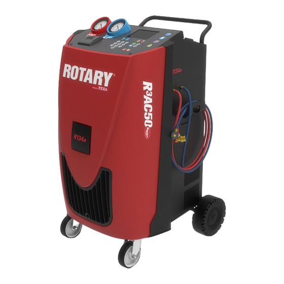
Page 20: Description
8 DESCRIPTION 1. Dashboard 2. Body of the recharging station 3. Castors with brakes )The Controller is built-in. - Page 21 4. High Pressure gauge (HP) 5. Low Pressure gauge (LP) 6. Display 7. Status LED • REC-GREEN:Recycling • VAC-BLUE:Vacuum • INJ-ORANGE:Injection • REF-RED:Charge 8. Printer 9. Keyboard )Optional...
- Page 22 10. Paper compartment lever 11. Paper compartment cover 12. Printer Status LED - GREEN 13. PAPER FEED button 14. ON/OFF button 15. ENTER and BACK/CANCEL buttons 16. UP and DOWN arrow buttons 17. Numeric keypad 18. STOP button 19. INFO button...
- Page 23 20. Handle 21. Set-up for WiFi module 22. SD CARD slot 23. Service hose holder 24. HP/LP quick couplers 25. Service hoses...
- Page 24 26. OIL PAG/POE bottle for specific oil 27. UV bottle for UV dye 28. DRAIN bottle for recovered oil 29. Service bulkhead to access the filter 30. Service bulkhead to access the pump 31. Wheels 32. Pneumatic connection 33. Tank cap 34.
- Page 25 35. Safety fuses: • Fast-acting fuse, 4 A • Time-delay fuse, 15 A • Time-delay fuse, 15 A 36. Power cable 37. Pump oil level sight 38. Main switch...
-
Page 26: Installation
9 INSTALLATION This chapter describes the procedures required to install the device properly. The installation must be performed by qualified personnel only, carefully following the instructions provided in this manual. The device is provided with the following: • Technical Manual: it contains the description of the device, user instructions to guarantee a correct use and correct maintenance. -
Page 27: Transportation Lock Removal
9.2 Transportation Lock Removal On the equipment there is a screw that blocks the internal tank's oil scales to preserve its integrity during transportation. This screw must be removed before starting to use the equipment. Proceed as follows: Proceed as follows: 1. -
Page 28: Handling
10 HANDLING This chapter describes the operations required to properly handle and position the equipment for use. 10.1 Moving the Device The equipment must be moved on its own wheels. The equipment was specifically designed and created to lower the center of gravity, so the heavier components were placed on the bottom;... -
Page 29: Positioning
10.2 Positioning The device must be placed near the A/C system that must be checked; make sure it is on a flat surface and in an appropriate environment, as specified in the safety regulations in this manual. Once the device has been positioned, we suggest locking the wheels with the specific mechanical brakes the wheels are equipped with. -
Page 30: Power Supply
11 POWER SUPPLY The equipment is powered by the mains through a specific power cable. The equipment must be connected to the mains through the supplied specific power cable; respect the applicable voltage, frequency and power values. The voltage, frequency and power values that can be applied can be found on the tag located near the main switch. -
Page 31: Power On/Off
12 POWER ON/OFF The equipment can be powered on and off using the main switch located on the left side of the charging station. To turn on the equipment, set the main switch to the I (ON) position. To turn off the equipment, set the main switch to the O (OFF) position. Do not disconnect the equipment from the mains by unplugging the power cable either from the equipment or from the socket. -
Page 32: Setting Up Before Using
To unlock the equipment, you must activate the product online. Alternatively, the equipment can be activated manually, requesting the unlock code via the Rotary Assistance Service. 13.2 Inserting the SD CARD The SD CARD contains the database of the vehicles on which it is possible to carry out air conditioning A/C system recharging operations and allows automatically storing each recharging service carried out. -
Page 33: How To Fill The Internal Tank
Fill the bottle with the correct type of oil. Proceed as follows: 1. Remove the desired bottle, slightly pulling back on the ferrule on the pneumatic coupler. 2. Unscrew the tank cap. 3. Fill the bottle with oil/UV tracer. 4. Screw the tank cap back on. 5. -
Page 34: Language Setup
13.6 Language Setup The software in the equipment can be displayed in different languages. The languages available are stored in the SD CARD. English is the default language. You must set the software's display language. This operation must be carried out when the equipment is started for the first time. You may change the language selected at any time by following the instructions provided in this chapter. - Page 35 5. Press 6. Press until you reach the desired language. 7. Press 8. The language is set.
-
Page 36: User Instructions
14 User Instructions This chapter provides various general instructions on how to use the device. 14.1 How to Connect to the Vehicle Air Conditioning System In order to carry out A/C system recharging operations you are required to connect the device to the vehicle. -
Page 37: How To Use The Software
14.4 How to Use the Software The software in the charging stations allows selecting the vehicle to work on choosing among the ones in the database and launching all the functions required in order to recharge and check the vehicle's A/C system. The keypad on the top panel of the device acts as an operator-machine interface and allows you to select and launch the functions available, enter specific data for the operation that needs to be carried out and, in general, allows you to complete all the operations the software permits. -
Page 38: Printer
14.5 Printer The buttons on the printer have the following functions: Button Name Function PAPER FEED It allows the paper to come out. ON/OFF It allows setting the printer on on-line/off-line mode. The printer is equipped with a green LED that indicates its status: •... -
Page 39: Updating
15 UPDATING This chapter describes the operations required in order to carry out an update on the database and/or operating system of the device. The update takes place through the provided SW R AC Update. You must have a PC with a USB port and an active Internet connection available. -
Page 40: Sd Card Update
15.2 SD CARD Update Through the SW R AC Update software you can update the contents of the SD CARD and, using the latter, then update the charging station. The software checks if there are updates available in Internet and allows you to download them. You must have an active Internet connection. - Page 41 8. Click on the icon. The software has been started. Icon Name Description Notes Service It allows you to access the advanced configuration options. Language update It allows you to update the languages available on the SD CARD. -- It allows you to update the database, the self-diagnosis software Update and the firmware in the SD CARD.
-
Page 42: Maintenance
16 MAINTENANCE This chapter describes the maintenance operations required for the device. Carefully follow the instructions provided in this manual. Only use original spare parts or approved by the manufacturer. For further help, contact your Retailer or the Technical Assistance service. - Page 43 1. Go behind the device. 2. Locate the service bulkhead to remove. 3. Loosen the four screws that block the bulkhead using a hexagonal wrench no. 3. 4. Remove the bulkhead.
-
Page 44: Dehydrator Filter Replacement
16.1.1 Dehydrator Filter Replacement The filter must be replaced when you are prompted to do so by the device. There could be accidental refrigerant leaks while replacing the filter. Carefully follow the instructions provided below to avoid the refrigerant from getting into the atmosphere. Wear appropriate protective glasses and gloves while replacing the filter. - Page 45 Proceed as follows: 1. When requested to, remove the service flap. 2. Open the filter's blocking clip. 3. Unscrew the 2 fixing nuts on the dryer filter using a specific metric fork wrench no. 19 and no. 22.14. 4. Remove the filter by slipping it from the right side. 5.
-
Page 46: Mechanical Filter Replacement
16.1.2 Mechanical Filter Replacement The mechanical filter when the dehydrator filter is replaced. The mechanical filter is located behind the dryer filter. Follow the same safety precautions indicated in the Dryer Filter Replacement chapter. a) Constant expansion valve connection - mechanical filter b) Mechanical filter. - Page 47 9. Open the filter using a metric fork wrench no. 24 and no. 28. 10. Remove the O-ring. 11. Remove the filter element. 12. Replace the filter element and O-rings. 13. Close the filter using a tightening torque of 30 N·m / 22 ft·lbs. 14.
-
Page 48: How To Replace The Vacuum Pump Oil
16.1.3 How to Replace the Vacuum Pump Oil The oil in the vacuum pump must be replaced when you are prompted to do so by the device. You must carefully read and understand this Operating Manual to perform the provided instructions correctly. a) Vacuum pump b) Filler cap c) Ground terminal... -
Page 49: Replacing The Paper In The Printer
16.1.4 Replacing the Paper in the Printer Follow the instructions provided in the chapter Replacing the Paper in the Printer. -
Page 50: Periodical Checks
16.2 Periodical Checks In order to guarantee proper operation of the device we recommend checking on a regular basis the parts that are the most subject to wear. Parts subject to Check wear Service hoses Make sure there are no cuts, scratches or bulges. Make sure there are no signs of wear and that the hoses do not harden during use. -
Page 51: Technical Features
17 TECHNICAL FEATURES Builder TEXA S.p.A. Brand ROTARY Model AC50 Fluid / Group R134a / 2 Electronic refrigerant scale (Precision) ± 0.35 oz / ± 10 g Oil quantity display resolution 0.7 oz / 20 ml Pressure transducer Class 1.0 High Pressure (HP) gauge Ø... -
Page 52: Data Plate
18 DATA PLATE Every single device is accompanied by an identification data plate just as the one in the example provided below: Where: • PS: maximum operating pressure; • TS: operating temperature. -
Page 53: Hydraulic Diagram
19 HYDRAULIC DIAGRAM... -
Page 54: Disposal
20 DISPOSAL Below you will find information on how to properly dispose of the device. 20.1 How to Dispose of the Device To dispose of the device proceed as follows: 1. Ask assistance personnel to collect all the refrigerant in the internal circuit, making sure the internal storage tank is emptied as well. -
Page 55: Contacts
Sales and Support: (800) 445-5438 Local: (812) 273-1622 Find us online at: WEB: www.rotarylift.com facebook/RotaryLift Instagram/rotarylift +49.771.9233.0 © VEHICLE SERVICE GROUP™ All Rights Reserved. Unless otherwise indicated, ROTARY, all the other trademarks are property of Dover Corporation and its affiliates.
Need help?
Do you have a question about the R3 AC50 and is the answer not in the manual?
Questions and answers
Machine asking to connect drain oil bottle. It is connected
The Rotary R3 AC50 machine may prompt to connect the drain oil bottle even when it is already connected if the bottle is not properly seated, the sensor is not detecting it correctly, or there is an issue with the bottle's identification or connection. Check that the correct bottle is used, it is fully inserted, and the sensor or connectors are clean and functioning properly.
This answer is automatically generated