
Summary of Contents for Systema EOLO BC RT
- Page 1 EOLO HOT AIR GENERATORS GAS ROOF TOP EOLO BC RT Condensing, modulating EOLO NBC RT Non-condensing, modulating Instruction manual installation, use and maintenance ENGLISH Cod. 10CNDE0063 Rev. 09ENIT04052021...
- Page 2 Before installation, check that the local distribution conditions, the type of the gas and the pressure are compatible with the regulation of the appliance. In order to improve the product, Systema reserves the right to modify its contents at your convenience and without notice.
-
Page 3: Table Of Contents
QUADRI COMANDO PER IL FUNZIONAMENTO DEL BRUCIATORE ..........30 4.1.1 Comando manuale con controllo non fornito da Systema ................... 30 4.1.2 Optional connections (room control panel not supplied by Systema) ..............30 4.1.3 Wiring diagram with a fan and three-phase AC asynchronous motor ..............31 4.1.4 Wiring diagram with two fans and three-phase AC asynchronous motors ............ - Page 4 OBJECT AND DURATION OF THE WARRANT ................. 84 10.2 WARRANTY EXCLUSIONS ......................... 84 10.3 EFFECTIVENESS AND EFFECTIVENESS OF THE WARRANTY ........... 84 10.4 RESPONSIBILITY ..........................84 PROVISION IS DISPOSAL ......................85 11.1 PROVISION ............................85 11.2 DISPOSAL ............................. 85 SYSTEMA EOLO RT rev. 09ENIT04052021...
-
Page 5: General Rules
It is compulsory to comply with the contents of this manual, particularly as regards safety standards. ■ Systema declines all responsibility for direct or indirect damage to persons, animals or things deriving from failure to ■ observe the instructions contained in this booklet. - Page 6 Installations with generator outside are possible, by requesting the appropriate version when ordering, up to an external air temperature of -20 ° C (outdoor version), below this value the operation of the appliance is no longer guaranteed. SYSTEMA EOLO RT rev. 09ENIT04052021...
-
Page 7: Terminology Used In The Manual
Command and control panel / terminal for the management of the devices through a serial system. The devices must be Master equipped with a SLAVE card for connection to the serial network. Slave Card (SCP674V202MB) installed on the machine equipped with a port for connecting the device to a serial network. Tab. 1.1 Defintions SYSTEMA EOLO RT rev. 09ENIT04052021... -
Page 8: Packaging
EOLO RT is designed for direct distribution or with channels air in the heated space. The channels can be made of aluminum, steel or elastic fabric. SYSTEMA ensures great flexibility regarding the air flow and the useful head of the appliances. The equip- ment supplied can contain different grids / air intakes, electrically controlled dampers, mixing chambers, filters, etc., depending on the installation. -
Page 9: Intended Use
Fig. 3.1 Device coding Example EOLO BC 150 RT PA1 Unit model EOLO 150 (155 kW), condensation (BC), prepared for roof top installation (RT), fan with belt drive, fixed flow rate and 200 Pa pressure (PA1). SYSTEMA EOLO RT rev. 09ENIT04052021... -
Page 10: Technical Specifications
The minimum operating temperature is -10°C, it is however possible to use the appliance with temperatures down to -20 ° C by applying the kit LOW TEMPERATURE (optional). Specify when ordering the request for the assembly of the LOW TEMPERATURE Kit. SYSTEMA EOLO RT rev. 09ENIT04052021... - Page 11 The minimum operating temperature is -10°C, it is however possible to use the appliance with temperatures down to -20 ° C by applying the kit LOW TEMPERATURE (optional). Specify when ordering the request for the assembly of the LOW TEMPERATURE Kit. SYSTEMA EOLO RT rev. 09ENIT04052021...
-
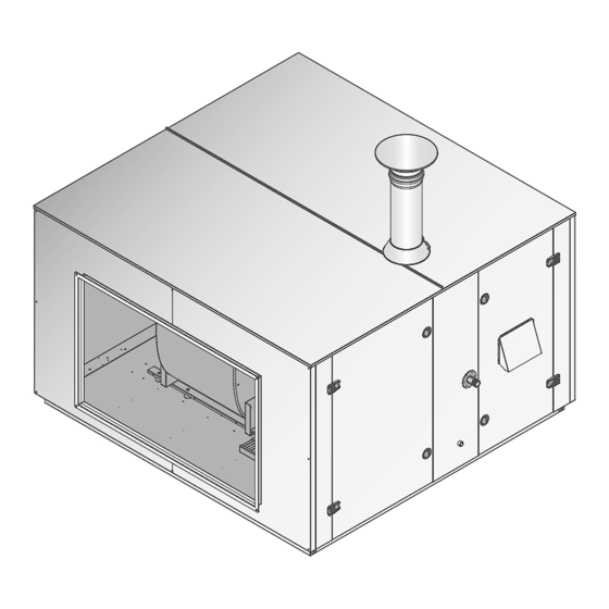
Page 12: Main Components Of The Appliance
1x3,80 1x4,25 Total nominal electric power 4,59 4,59 3,89 4,02 4,02 4,50 Fan model may change depending on current product availability Tab. 3.3 Principles of components for BC / NBC version devices (1 of 2) SYSTEMA EOLO RT rev. 09ENIT04052021... - Page 13 2x4,25 2x4,25 Total nominal electric power 4,50 4,50 4,54 8,82 8,97 8,98 Fan model may change depending on current product availability Tab. 3.3 Principles of components for BC / NBC version devices (2 of 2) SYSTEMA EOLO RT rev. 09ENIT04052021...
-
Page 14: Identification Plate And Information Labels
Category: X X X X TYPE: DESTINATION 70LENX0100 XXXXXXXXX XXXXXXX Document int. PWProd/PWT1/2020 XXXXXXXXXXXXXXX XXXX XXX XX XXXXXXX SYSTEMA EOLO RT rev. 09ENIT04052021 Read the installation instructions before installing and switching on the appliance. For type B applications, please forsee... - Page 15 Fig. 3.3 Position of the identification plate, the warning label, the external label of the instruction manual and the labels XXXXXXX to be used for fuel changes XXXXXXXXXX YYYYYYYY XXXXXX Device adjusted for: SYSTEMA X X X X EOLO RT rev. 09ENIT04052021 Category: X X X X TYPE:...
-
Page 16: Overall Dimensions
FRONT VIEW (AIR SUPPLY) SIDE VIEW (ACCESS TO THE BURNER AND FANS COMPARTMENTS) QUOTE IN MM REAR VIEW (INLET AIR) REAR VIEW (INLET AIR VER. MIXING CHAMBER) Fig. 3.4 Overall dimensions of the basic version SYSTEMA EOLO RT rev. 09ENIT04052021... - Page 17 2392 2392 2392 3492 1504 1745 2193 2500 2500 2500 3600 1400 1200 1400 1600 2000 1000 1000 1000 1500 ØS 1000 1000 1000 1000 1000 1500 Tab. 3.6 Overall dimensions of the basic version SYSTEMA EOLO RT rev. 09ENIT04052021...
-
Page 18: Main Components
AIR INTAKE SIDE - VERSION 1-WAY INTAKE Fig. 3.5 Main components - version with 1-way air intake AIR INTAKE SIDE - VERSION MIXING CHAMBER 2-WAY AIR INTAKE Fig. 3.6 Main components - version with mixing chamber SYSTEMA EOLO RT rev. 09ENIT04052021... - Page 19 Internal air intake (optional - double intake version) Burner Air delivery Condensate drain (BC version only) Exchanger Gas connection Main disconnector and control panel connection terminal block Access door to the fan housing compartment Tab. 3.7 SYSTEMA EOLO RT rev. 09ENIT04052021...
-
Page 20: Eolo Bc / Nbc Burner 15 ÷ 65 Rt
FEATURES EOLO BC / NBC BURNER 15 ÷ 65 RT Fig. 3.8 Exploded view of burner for Eolo mod. BC / NBC 15 ÷ 65 RT SYSTEMA EOLO RT rev. 09ENIT04052021... - Page 21 Ghiera aria secondaria Eolo 35 94CNOP0026 Vite bloccaggio mixer aria/gas 10WSSR2095 Ghiera aria secondaria Eolo 45 94CNOP0025 Mixer aria/gas 94CNMI0013 Tab. 3.8 Exploded view of burner for Eolo mod. BC / nbc 15 ÷ 65 RT SYSTEMA EOLO RT rev. 09ENIT04052021...
-
Page 22: Eolo Bc / Nbc Burner 85 ÷ 120 Rt
Injector connection and gas nozzle holder 94ARSZ6006 Air / gas mixer ring nut tightening screw 10WSSR2111 Gas pressure switch (optional) 05CEPR0317 Tab. 3.9 Exploded view of burner for Eolo modd. BC / BL 85 ÷ 120 RT SYSTEMA EOLO RT rev. 09ENIT04052021... -
Page 23: Burner Eolo Bc / Nbc 150 ÷ 300 Rt
Honeywell Venturi mixer Code 94CNIM0014 94CNIM0015 94CNIM0016 94CNIM0016 Gas connection Code 94ARPG6000 94ARPG6000 94ARPG6000 94ARPG6000 Honeywell minimum and maximum gas Code 00CEPR1151 00CEPR1151 00CEPR1151 00CEPR1151 pressure switch Gas solenoid valve Code 94CEVA0004 94CEVA0004 94CEVA0005 94CEVA0005 Tab. 3.10 SYSTEMA EOLO RT rev. 09ENIT04052021... -
Page 24: Standard Fan Section
Three-phase electric motor Anti-vibration cushions Motor pulley V-belt tension adjuster screw V-belt Motor slide guides Fan pulley Engine support plate with belt tensioner Tab. 3.11 3.13 EC PLUG FAN SECTION Fig. 3.12 EC plug fan SYSTEMA EOLO RT rev. 09ENIT04052021... -
Page 25: Supply And Air Intake Accessories (Optional)
3.14 SUPPLY AND AIR INTAKE ACCESSORIES (OPTIONAL) Fig. 3.13 Air delivery and return accessories (optional) Important Cleaning or replacing the filters (14) is essential to ensure proper operation unit and the correct air flow rate. SYSTEMA EOLO RT rev. 09ENIT04052021... - Page 26 85 RT; 100 RT; 120 RT 91RTAK1037 Intake grill for 2 ways panel 150 RT 91RTAK1038 200 RT 91RTAK1039 250 RT 91RTAK1040 300 RT 91RTAK1041 Tab. 3.12 List of air intake and deliveries accessories optional (1 of 3) SYSTEMA EOLO RT rev. 09ENIT04052021...
- Page 27 85 RT; 100 RT; 120 RT 91RTAK1061 Curva di mandata destra/sinistra 150 RT 91RTAK1062 200 RT 91RTAK1063 250 RT 91RTAK1064 300 RT 91RTAK1065 Tab. 3.12 List of air intake and deliveries accessories optional (2 of 3) SYSTEMA EOLO RT rev. 09ENIT04052021...
- Page 28 85 RT; 100 RT; 120 RT 91RTAK1092 2-way air damper by-pass type 150 RT 91RTAK1093 200 RT 91RTAK1094 250 RT 91RTAK1095 300 RT 91RTAK1096 Tab. 3.12 List of air intake and deliveries accessories optional (3 of 3) SYSTEMA EOLO RT rev. 09ENIT04052021...
-
Page 29: Electrical System
Connect the power supply (3N / PE ~ 50Hz 400V) to the isolator located on the panel on board the thermal unit. Fig. 4.1 Connecting the power supply SYSTEMA EOLO RT rev. 09ENIT04052021... -
Page 30: Quadri Comando Per Il Funzionamento Del Bruciatore
Operation is 'two-stage' according to parameter Y6 (see tab. 5.3 on p. 56). Setting value 0 (zero) excludes 'two-stage' operation and activates 'one-stage' operation. 4.1.2 Optional connections (room control panel not supplied by Systema) Fig 4.2 Room thermostat panel connections and burner power adjustment (optional) MOD = BURNER POWER ADJUSTMENT... -
Page 31: Wiring Diagram With A Fan And Three-Phase Ac Asynchronous Motor
ELECTRICAL CONNECTION 4.1.3 Wiring diagram with a fan and three-phase AC asynchronous motor since January 2023 ROOM CONTROL PANEL SUPPLY (see fig. 4.2 p. 30) 3N/PE~50Hz 400V Fig 4.3 Wiring diagram. SYSTEMA EOLO RT rev. 09ENIT04052021... -
Page 32: Wiring Diagram With Two Fans And Three-Phase Ac Asynchronous Motors
F3 = Burner protection fuse M3f-2 = Second three-phase centrifugal fan motor F4 = Fuse burner protection P3 = Probe NTC 100 inlet air flow temperature F5 = Fuse auxiliary protection J5B - J6B F-M1 = Fan thermal protection SYSTEMA EOLO RT rev. 09ENIT04052021... -
Page 33: Optional Components
Fig. 4.6 Mainboard SCP674V130A1 CONNECTED CONNECTOR TERMINAL DESCRIPTION COMPONENT Power supply (L) XS-L3 connector Power supply (N) XS-N connector Ground connection XS connector Ground connection Ground connection Tab 4.1 SCP674V130A1 card connections legend (1 of 3) SYSTEMA EOLO RT rev. 09ENIT04052021... - Page 34 Ts), minimum air flow pressure switch with manual reset (optional), maximum gas pressure switch (optional, standard for models 150 ÷ 300) Tso, Pa, Pg (if present) Tab 4.1 SCP674V130A1 card connections legend (2 di 3) SYSTEMA EOLO RT rev. 09ENIT04052021...
- Page 35 Reset on SLAVE (SCP674V124, SCP674V143, SCP674V202) SLAVE (J1; K1) Connector XS2-11 Contacts for summer ventilation Connector XS2-12 —- Bridge contact —- Pp (connected only during Programming button board programming) Tab 4.1 SCP674V130A1 card connections legend (3 di 3) SYSTEMA EOLO RT rev. 09ENIT04052021...
-
Page 36: Automatic Control (With Optional Panels Supplied By Systema)
ELECTRICAL CONNECTION 4.1.7 Automatic control (with optional panels supplied by Systema) REFERENCE SLAVE (optional) ROOM CONTROL PANEL THERMAL POWER CONTROL SCHEME Chronothermostat for controlling a single RT appliance with automatic burner modulation Mod. SCP674V202 Fig. 4.8, pag. 42 based on room temperature and Fig. -
Page 37: Wiring Diagram With Scp674V122T Terminal And Slave Mod. Scp674V202
ELECTRICAL CONNECTION 4.1.8 Wiring diagram with SCP674V122T terminal and slave mod. SCP674V202 SYSTEMA EOLO RT rev. 09ENIT04052021... -
Page 38: Wiring Diagram With Scp674V122T Terminal And Slave Mod. Scp674V202
Wiring diagram with SCP674V122T terminal and slave mod. SCP674V202 POWER SUPPLY 3N/PE~50Hz 400V Ground panel figs. 4.17, 4.18, on pages 52 and 53 Fig. 4.8 Wiring diagram with SCP674V202 slave card for managing the appliance via I²NET and / or SCP674V122T room terminal SYSTEMA EOLO RT rev. 09ENIT04052021... - Page 39 674V122T (Hd2) XS2 = Terminal block placed in the burner housing com- P3 = Probe NTC 100 inlet air flow temperature partment Please note For appliances with two fans see also fig. 4.4 on page 36. SYSTEMA EOLO RT rev. 09ENIT04052021...
-
Page 40: Variant For Connecting Fans With Soft-Start (Optional)
APPLIANCES WITH ONE FAN AND THREE-PHASE AC ASYNCHRONOUS MOTOR Connection to motherboard SCP674V130A1 POWER SUPPLY 3N/PE~50Hz 400V Fig. 4.10 Electrical connection of a fan with soft-start Please note For the complete wiring of the appliance see also paragraphs 4.1.3 to 4.1.9. SYSTEMA EOLO RT rev. 09ENIT04052021... - Page 41 M3f-1 = Three-phase centrifugal fan motor XS = Power line terminal board located in the burner hou- M3f-2 = Second three-phase centrifugal fan motor MS1 = sing Free opening mechanism SYSTEMA EOLO RT rev. 09ENIT04052021...
-
Page 42: Electrical Connection Of Plug Fan (Optional) With Potentiometer
Connection to motherboard SCP674V130A1 Plug fan POWER SUPPLY 3N/PE~50Hz 400V Fig. 4.12 Electrical connection of a plug fan with potentiometer Please note For the complete wiring of the appliance see also paragraphs 4.1.3 to 4.1.9. SYSTEMA EOLO RT rev. 09ENIT04052021... -
Page 43: Electrical Connection With Plug Fan (Optional), Automatic Operation
RV = 10 kΩ potentiometer for manual plug fan speed mo- Ts = Safety thermostat with automatic reset dulation XS = Power line terminal board located in the burner hou- SG = General switch (see fig. 4.1 on page 33) sing SYSTEMA EOLO RT rev. 09ENIT04052021... -
Page 44: Scp674V202 Slave Card Connections
RS 485 Sc Bus connector for connection to the network, to be used only in the case of management via network I2NET and Network Master Controller (SCM830 XS2-2 connector / 850) XS2-1 connector Tab 4.3 Legend for SCP674V202 slave card connections SYSTEMA EOLO RT rev. 09ENIT04052021... -
Page 45: Connection With Master Controller For I²Net Network
POWER SUPPLY 3N/PE~50Hz 400V Twisted shielded cable for con- nection of the square to eartg ge- nerators with minimum section CONNESSIONE DI RETE Fig. 4.17 Connection with ground control panel of the I²NET networ SYSTEMA EOLO RT rev. 09ENIT04052021... -
Page 46: Connection Of The I²Net Network Panel To Earth And Scp674V122T Panel
Enable the end-of-line resistor by setting dip1 of SW4 on the slave card to ON only in the last network card, the one furthest away from the master device Fig. 4.18 Connection with ground control panel of the I²NET network and SCP674V122T panel SYSTEMA EOLO RT rev. 09ENIT04052021... -
Page 47: Operation Of The Appliance
Screw and spring terminals for wires 1 PWM output; with a max. cross-section of 1.5 mm Data output: TTL serial iFS interface J1A / J1B terminal blocks for wires with a max. cross-section of 4 mm Display: 2-digit display. SYSTEMA EOLO RT rev. 09ENIT04052021... -
Page 48: Operation Indicators On The Display
/ rH / Y9 with the data provided by the burner manufacturer, switch off the power supply to the board for at least 10 seconds. Alarm EEPROM alarm faulty; try switching the instrument off and on again. Tab 5.1 Indications on the display of the SCP674V030 board SYSTEMA EOLO RT rev. 09ENIT04052021... -
Page 49: Burner Operating Parameters
Tab 5.3 Burner operating parameters Please note Modification of these parameters should only be carried out by authorised or factory service. Incorrect parameters may cause damage to the appliance and, in extreme cases, fire and risk to human life. SYSTEMA EOLO RT rev. 09ENIT04052021... -
Page 50: Board Operation
See paragraphs 5.1.3 and 5.1.4 on pages 61 and 62 for the description of the parameters (Y0, Y1, etc.). See paragraph 4.1 from page 39 to page 55 for the description of the components (Ts, Mac1, etc.) SYSTEMA EOLO RT rev. 09ENIT04052021... -
Page 51: Burner Shutdown Due To Opening Of A Safety Contact
The flame controller device is a manual type. To reset the burner controller press the Sr button for at least 2 seconds or send the signal to SCP674V131MB board from terminal or close the reset contact RT (connector J9B). Tab 5.7 Fault sequence - safety devices intervention SYSTEMA EOLO RT rev. 09ENIT04052021... -
Page 52: Scp674V202 Slave Board Programming
Fig. 5.3 DIP Switch position on the SCP674V202 slave board SW1 position (rotary) SLAVE address (module SCO674V202) SW2 (DIP 1 and 2) 0...F 0...15 0...F 16...31 0...F 32...47 0...F 48...59 Tab 5.13 Address network interface SYSTEMA EOLO RT rev. 09ENIT04052021... -
Page 53: Dip Swicht Configuration 3
IMPORTANT Do not enable timer and the external network probe at the same time the deactivation of the network port in order not to compromise the operation of the board. SW1 = F = WRONG SYSTEMA EOLO RT rev. 09ENIT04052021... -
Page 54: Scp674V202 Slave Coding For Single Device With Scp674V122T Terminal
The lack of the probe, if active, generates an error on the network controller. If you enable network probes 1 and / or 2, check that the network controller has set the correct network probe addresses. SYSTEMA EOLO RT rev. 09ENIT04052021... -
Page 55: Configuration Of Operating Parameters Scp674V202
To exit programming press RETURN or Reset relay activation, burner reset start wait 30 seconds without acting on the keypad for automatic exit Set point (comfort / economy) Parameter menu Timer menu Tab 5.19 Menus and submenus SYSTEMA EOLO RT rev. 09ENIT04052021... -
Page 56: List Of Operating Parameters Scp674V202
Minimum outside temperature value for calculation of automatic correction algorithm for -20…Ln8 °C parameter LrH, 'LrA'. Maximum outside temperature value for calculation of automatic correction algorithm for Ln6…15 °C parameter LrH, 'LrA'. Tab 5.20 Operating parameters SCP674V202 (1 of 2) SYSTEMA EOLO RT rev. 09ENIT04052021... - Page 57 0 = function NOT ENABLED 1 = function enabled Firmware Release (READ ONLY) ☺ Keypad lock. NO=NO; YES=YES ☺ NO..YES Tab 5.20 Operating parameters SCP674V202 (2 of 2) SYSTEMA EOLO RT rev. 09ENIT04052021 Tab 7.13 Operating parameters SCP674V202 (2 of 2)
-
Page 58: Gas Pipe
Supply gas pressure adjustment: all appliances are tested and calibrated in the factory for the pressures for which they are designed (see burner plate data or paragraph 8.5 on page 92). WARNING Seal the gas solenoid valve adjustment part after calibration. SYSTEMA EOLO RT rev. 09ENIT04052021... - Page 59 Maximum gas pressure switch with manual reset (40 mbar) - optional (standard for models 120 ÷ 300) Minimum gas pressure switch (20 mbar) - optional (standard for models 120 ÷ 300) Tab 6.1 Gas train components SYSTEMA EOLO RT rev. 09ENIT04052021...
-
Page 60: Installation
Eolo units are equipped with a special profile dedicated to the forklift. Before placing the unit on the structure, both the two rails and the four transport feet must be removed. (fig. 7.1) transport feet Fig. 7.1 Holes for handling SYSTEMA EOLO RT rev. 09ENIT04052021... -
Page 61: Handling Of Units With Separate Sections
Eolo units can be shipped with separate burner and fan sections. In this case it is possible to move the sections of the unit with the aid of a forklift. Fig. 7.3 Handling of units with separate sections SYSTEMA EOLO RT rev. 09ENIT04052021... -
Page 62: Assembly Of The Burner / Fans Sections
INSTALLAZIONE ASSEMBLAGGIO SEZIONI BRUCIATORE/VENTILATORI Connect the 24 pin M8x20 mm Collegare il connector connettore 24 pin Ø4,2x16 mm Fig. 7.4 Assemblaggio sezioni separate Fig. 7.4 Assembly of separate sections SYSTEMA S.P.A. EOLO RT rev. 09ITIT04052021 SYSTEMA EOLO RT rev. 09ENIT04052021... -
Page 63: Service Acces
(buffer zone) Respect area Fig. 7.6 Respect area Dimension U.M. 25/35 45/65 85/100/120 1000 1100 1100 1100 1250 1000 1100 1100 1100 1250 1000 1000 1100 1300 Tab. 7.1 Respect area SYSTEMA EOLO RT rev. 09ENIT04052021... -
Page 64: Condensate Drain
Condensate stagnation in the exchanger Install the appliance perfectly level to maintain the natural inclination of the tube bundle and allow the ■ condensate to drain, preventing it from accumulating inside the exchanger during normal operation SYSTEMA EOLO RT rev. 09ENIT04052021... -
Page 65: Frost Protection
. Important To carry out the condensate drain, always refer to the prescriptions of the regulations in force since in some countries all the types of drain described are not allowed. SYSTEMA EOLO RT rev. 09ENIT04052021... -
Page 66: Testing And Start-Up Of The Plant
After 10 seconds, the appliance can be unlocked by resetting the burner control equipment. 7) After opening the gas solenoid valve, the burner ignites 8) After the stabilization of the working conditions (about 15 min.), Carry out a combustion analysis and a SYSTEMA EOLO RT rev. 09ENIT04052021... -
Page 67: Adjustments
OFFSET again. 4) Final check of combustion. 5) Seal the screws (6) and (9). WARNING Seal the gas valve adjustment part after calibra- tion. Fig. 8.1 Solenoid valve 848 Sigma SYSTEMA EOLO RT rev. 09ENIT04052021... -
Page 68: Regolazioni Su Apparecchi Con Elettrovalvola 822 Nova Mix
OFFSET again with the screw (4) 4) Final combustion check 5) Seal the screws (7) and (4). WARNING Fig. 8.2 822 Nova Mix solenoid valve Seal the gas valve adjustment part after calibration. SYSTEMA EOLO RT rev. 09ENIT04052021... -
Page 69: Air Mixer (Eolo Bc / Bl 15 ÷ 120 Rt)
The air regulation must not be modified unless indicated by the manufacturer. POS. DESCRIPTION Air / gas mixer Gas inlet Secondary air regulator tightening screw Primary air inlet Secondary air regulator Secondary air inlet Tab. 8.3 Burner fan legend Fig. 8.3 Burner fan SYSTEMA EOLO RT rev. 09ENIT04052021... -
Page 70: Adjustment Of Burner Parameters With Solenoid Valve Type Vr4
"OFFSET" minimum pressure adjustment Measurement of the gas pressure on the burner Pressure measurement at the supply Tab. 8.4 Fig. 8.4 Adjustment of the burner parameters in the Eolo BC / BL 150 ÷ 300 RT models SYSTEMA EOLO RT rev. 09ENIT04052021... -
Page 71: Maximum Adjustment And Fine Adjustment
To ensure class 5 of NO emissionsX, the value λ must have a maximum thermal load of not less than 1.3. The measurement of NOX (3% of O2) with the value of λ equal to 1.3 gives results below 30 ppm. SYSTEMA EOLO RT rev. 09ENIT04052021... -
Page 72: Features For Vr Gas Solenoid Valves
COLLAUDO 8.3.5.3 Features for VR gas solenoid valves ... Honeywell solenoid valve mod. VR 415 (Eolo 150) ∆ fig. 8.5 SYSTEMA EOLO RT rev. 09ENIT04052021... - Page 73 COLLAUDO oneywell solenoid valve mod. VR 420 (Eolo 200; Eolo 250) ∆ Fig. 8.6 SYSTEMA EOLO RT rev. 09ENIT04052021...
- Page 74 COLLAUDO Honeywell solenoid valve mod. VR 425 (Eolo 300 BC / BL RT) ∆ Fig. 8.7 SYSTEMA EOLO RT rev. 09ENIT04052021...
-
Page 75: Position Of Electrodes
COLLAUDO POSITION OF ELECTRODES For correct ignition and flame detection, the electrodes must be positioned inside the combustion cone in the position indicated in the drawing. Fig. 8.9 Electrode position SYSTEMA EOLO RT rev. 09ENIT04052021... -
Page 76: Tensioning The Transmission Belts
V-belts after 2-4 working hours. If ne- cessary, correct as described 1000 L [mm] Fig. 8.11 Diagram of the tensioning force of the Fig. 8.12 Dimension symbols for the diagram of the straps belt tensioning force. SYSTEMA EOLO RT rev. 09ENIT04052021... -
Page 77: Maintenance
Important Put the system back into operation once the maintenance operations have been completed. SYSTEMA EOLO RT rev. 09ENIT04052021... -
Page 78: Fuel Change
Changing the supply gas pressure does not cause a change in the rated output of the burner. After changing the type of gas, adjust as described in paragraphs 8.3.4 and 8.3.5 on pages 85 and 86. WARNING Seal the gas valve adjustment part after calibration. SYSTEMA EOLO RT rev. 09ENIT04052021... -
Page 79: Anomalies And Remedies
The operation can be carried out by assistance or by authorized and qualified personnel. 15) Check parameter Y2 and / or set it by increasing it gradually until 15) Wrong parameters of the PWM burner in burner ignition correct ignition CONTINUED ON NEXT PAGE SYSTEMA EOLO RT rev. 09ENIT04052021... - Page 80 28) Check the correct connection of the probes and / or replace them 28) Air temperature probes faulty or not connected correctly with original spare part 29) Faulty fans 29) Replace with original spare part CONTINUED ON NEXT PAGE SYSTEMA EOLO RT rev. 09ENIT04052021...
- Page 81 32) Broken ventilation belts 32) Replace with original spare part 33) Check and set the tensioning of the belts as indicated in paragraph 33) Wrong belt tension 9.7 on page 86 SYSTEMA EOLO RT rev. 09ENIT04052021...
-
Page 82: Warranty
EXPRESSLY EXCLUDING ANY OTHER FORM OF WARRANTY OR INDEMNITY, BOTH LEGAL OR CONVENTIONAL. The replaced parts will be promptly returned to SYSTEMA, ex its factory in Zdunska Wola - Poland, at the user's expense and expense. In the event of an intervention under Warranty, the user will be responsible for the fixed right of call, in addition to the kilometer reimbursement, if the place of intervention is more than ten kilometers from the CA (As- sistance Center) headquarters. -
Page 83: Provision Is Disposal
If the piping is not dismantled, seal the terminals where the appliances were connected with threaded caps. SYSTEMA EOLO RT rev. 09ENIT04052021... - Page 84 Business name VAT number Address Common province Phone E-mail 3. APPLIANCE DATA Template Min/Max heat output [kW] Fuel □ □ Type exhaust and intake ducts □ □ □ Internal Indoor / outdoor instalattion □ External SYSTEMA EOLO RT rev. 09ENIT04052021...
- Page 85 Check that the safety devices are not tampered with and / or short-circuited Negative □ Not verified □ Positive □ Check that the temperature regulation system is working Negative □ Not verified □ Can the appliance be put into operation? □ Comments regarding commissioning: SYSTEMA EOLO RT rev. 09ENIT04052021...
- Page 86 (*) The intervention of the thermostat Ts causes the appliance to stop, to restart it, it is necessary to act on the reset button (Sr). In the case of a Tso thermostat equipped with manual reset, before pressing the reset button (Sr), the thermostat must be reset to restore operation of the appliance. SYSTEMA EOLO RT rev. 09ENIT04052021...
- Page 87 Maintenance is recommended by _________________________ Arrival / departure time at the plant _____________ / _____________ Technician who carried out the check: Name e Surname ___________________________ Legible signature of technical ___________________________ Legible signature, for acknowledgment, of the plant manager ___________________________ SYSTEMA EOLO RT rev. 09ENIT04052021...
- Page 88 In order to improve the quality of its products, Systema reserves the right to modify their characteristics without notice. SYSTEMA Polska Sp. z o.o. ul. Długa 5, 98-220 Zduńska Wola PL. +48.43.8247287 systema@systemapolska.pl www.systemapolska.pl...
Need help?
Do you have a question about the EOLO BC RT and is the answer not in the manual?
Questions and answers