
Summary of Contents for abaco systems NETernity RM921N
- Page 1 sales@artisantg.com artisantg.com (217) 352-9330 | Visit our website - Click HERE...
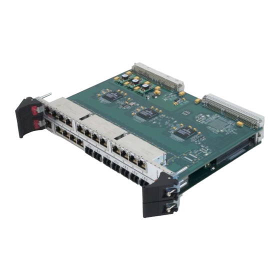
- Page 2 Hardware Reference Manual NETernity* RM921N / RM921ND VME Managed Ethernet Switch, IPv6-Capable, Layer 2/3+, 12/24 Port Gigabit, OpenWare* Switch Management Publication No. 597-0000000013-000 Rev. F...
- Page 3 WEEE is processed in accordance with the requirements of the WEEE Directive. Abaco Systems will evaluate requests to take back products purchased by our customers before August 13, 2005 on a case by case basis. A WEEE management fee may apply.
-
Page 4: About This Manual
About This Manual Conventions Notices This manual may use the following types of notice: WARNING Warnings alert you to the risk of severe personal injury. CAUTION Cautions alert you to system danger or loss of data. NOTE Notes call attention to important features or instructions. Tips give guidance on procedures that may be tackled in a number of ways. - Page 5 Further Information Abaco Website You can find information regarding Abaco products on the following website: LINK https://www.abaco.com Abaco Documents This document is distributed via the Abaco website. You may register for access to manuals via the website. LINK https://www.abaco.com/products/neternity-rm921n/p1222 NOTE Technical literature describing components used on the RM921N is available from the manufacturers’...
-
Page 6: Table Of Contents
Contents About This Manual ........................3 1 • Overview ........................... 8 1.1 Features ................................9 1.1.1 Product Features ................................9 1.1.2 Switch Fabric Features ..............................9 1.2 System Management Support ........................... 9 1.3 Safety Summary ............................... 10 1.3.1 Do Not Operate in an Explosive Atmosphere ........................ 10 1.3.2 Keep Away from Live Circuits ............................ - Page 7 List of Figures Figure 2-1 RM921N Front Panels ..........................13 Figure 2-2 Serial Console Port ............................ 14 Figure 2-3 Serial Console Port LEDs’ Location ......................14 Figure 3-1 Baseboard Block Diagram ......................... 17 Figure 3-2 DA921 with Removable Secure Memory ....................18 6 NETernity* RM921N / RM921ND Hardware Reference Manual Publication No.
- Page 8 List of Tables Table 2-1 Front Panel LEDs ............................12 Table 2-2 Serial Console Port (P13) Pin Descriptions ....................14 Table 2-3 Serial Console Port (P13) LEDs ........................14 Table 2-4 Board-to-VME Backplane Connector (P1) Pin Description ................ 15 Table 2-5 Board-to-VME Backplane Connector (P2) Pin Description ................ 15 Table B-1 Specifications for RM921N ........................
-
Page 9: Overview
1 • Overview The NETernity* RM921N is a full wire speed, Managed Layer 2/3 switch with Abaco’s exclusive OpenWare* switch management environment. The RM921N provides an all‐Gigabit Ethernet solution for high availability VME systems with an option to support 100Base-FX Ethernet connections. The boards feature 12 or 24 ports of GbE (Gigabit Ethernet) or 100Base-FX. -
Page 10: Features
1.1 Features 1.1.1 Product Features • 6U VME form factor • Layer 2/3 Switching • 12 Port Gigabit /100Base-FX Switch [single slot] • 24 Port Gigabit /100Base-FX Switch [dual slot] • Fully managed solution • Full IPv6 Compatibility • Combination of copper or fiber ports •... -
Page 11: Safety Summary
1.3 Safety Summary The following general safety precautions represent warnings of certain dangers of which Abaco Systems is aware. Failure to comply with these or with specific Warnings and/or Cautions elsewhere in this manual violates safety standards of design, manufacture and intended use of the equipment. Abaco Systems assumes no liability for the user’s failure to comply with these requirements. -
Page 12: Unpacking And Installation
2 • Unpacking and Installation This chapter describes the handling, installation, front panel and baseboard‐to‐ backplane connectors of the RM921N board. 2.1 Unpacking Procedures On receipt of the shipping container, check for any evidence of physical damage. All claims arising from shipping damage should be filed with the carrier and a complete report sent to Abaco Technical Support, see Technical Support Contact Information. -
Page 13: Front Panel Connectors And Indicators
2.5 Front Panel Connectors and Indicators 2.5.1 Network Connections There are three types of network connections used in the product family: • RJ45 connectors for 10/100/1000 MByte/s TX (copper) ports • LC connections for Fiber ports • RJ45 Connector for console port All RJ45 connectors are wired per industry specification;... -
Page 14: Figure 2-1 Rm921N Front Panels
Figure 2-1 RM921N Front Panels NOTE The front panels from left to right are: The first front panel with 8 Gigabit Copper ports and 4 Gigabit Fiber ports; the second front panel is the Expansion Panel with 12 Gigabit Copper ports, and the third front panel is 8 Gigabit Copper ports and 4 100FX Fiber. -
Page 15: Serial Console Port
2.5.3 Serial Console Port The baseboard provides a serial port through an RJ45 with integrated LEDs in the front panel (P13). This port is used for serial communication with the management board. Figure 2-2 Serial Console Port Table 2-2 Serial Console Port (P13) Pin Descriptions Pin No. -
Page 16: Baseboard-To-Vme Backplane Connector
2.5.4 Baseboard-to-VME Backplane Connector The RM921N base module interconnects with the VME backplane through the P1 and P2 connectors. P1 and P2 are standard DIN triple‐row, 96‐pin male connectors. Table 2-4 Board-to-VME Backplane Connector (P1) Pin Description Pin No. Name Description Comments A9, A11, A15, A17,... -
Page 17: Theory Of Operation
3 • Theory of Operation The RM921N is a VME‐based managed Ethernet switch with 12/24 port Gigabit, Layer 2/3, supporting IPv6. Moreover, the RM921N supports 100Base-FX interfaces through different hardware configurations. The management entity executes on an embedded processor. With a single slot solution, the baseboard supports 12 ports for GbE or 100Base-FX or a combination of both. -
Page 18: Figure 3-1 Baseboard Block Diagram
Figure 3-1 Baseboard Block Diagram Publication No. 597-0000000013-000 Rev. F Theory of Operation 17... -
Page 19: Figure 3-2 Da921 With Removable Secure Memory
Figure 3-2 DA921 with Removable Secure Memory NOTE The removable memory module is only available on the RM921ND. 18 NETernity* RM921N / RM921ND Hardware Reference Manual Publication No. 597-0000000013-000 Rev. F... -
Page 20: Switch Software Environment
3.2 Switch Software Environment The Switch Control services execute within the context of a standard Linux kernel. Using Linux as the basis for services has a number of advantages. On powerup, the Linux kernel goes through the basic initialization steps. Local configuration information is loaded from files saved on the switch. -
Page 21: Virtual Lan (Vlan)
Layer 3 and above, use information from the IP header. This can be an IP address, optionally qualified by port number. When a packet arrives, where the destination is not in the switch fabric database, it is “flooded” to applicable ports (i.e., VLAN setup may restrict the ports to which the packet will be forwarded). -
Page 22: Port Mirror
3.3.5 Port Mirror A Port Mirror is a mechanism which provides a method to observe traffic that is flowing on one port from another port. This can be very useful in a debug situation. If there is no access to a connection, a mirror‐to port can be created that can be attached to an external analyzer. -
Page 23: A • Compliance
A • Compliance A.1 Emission Compliance Notice This equipment complies with the following international and North American emission requirements: • Australia and New Zealand — AS/NZS 3548/CISPR 22 Class A ITE WARNING This is a Class A product. In a dramatic environment, this product may cause radio interference in which case the user may be required to take adequate measures. -
Page 24: Optical/Laser Device Notice
A.2 Optical/Laser Device Notice For optical/laser devices read the following note, caution, and warnings: WARNING For this product, use only the Class 1 laser devices that have the following approval: – FDA21 CFR 1040.10 – IEC 60825-1 NOTE Protect optical devices by inserting clean dust plugs into the device after the cables are extracted from them. -
Page 25: B • Specifications
B • Specifications Table B-1 Specifications for RM921N Power 31 Watts (12 copper ports) / 46 Watts (24 copper ports) 9.2 Amp (Max) @ 5V 26 Watts (12 fiber ports) / 37 Watts (24 fiber ports) 7.2 Amp (Max) @ 5V Form Factor 6U Single Slot MTBF... -
Page 26: C • Statement Of Volatility
C • Statement of Volatility C.1 Volatile Memory This product contains volatile memory, i.e., memory in which the contents are lost when power is removed. Volatile memory devices listed below are physically located on the DA921 daughter card. Table C-1 Volatile Memory Type of Memory Size User Modifiable... -
Page 27: Media Storage
C.3 Media Storage This product contains media storage capability, e.g., removable or nonremovable disk drives, memory cards, etc. Media storage device listed below is physically located on the DA921 daughter card. Table C-3 Media Storage Type of Size User- Function Process to Clear Memory Modifiable... - Page 28 Abaco Systems Additional Resources All rights reserved. Information Centers For more information, please visit the * indicates a trademark of Abaco Systems, Inc. and/or its affiliates. All other Abaco Systems web site at: Americas: trademarks are the property of their 1-866-652-2226 (866-OK-ABACO) respective owners.
Need help?
Do you have a question about the NETernity RM921N and is the answer not in the manual?
Questions and answers