Advertisement
Quick Links
Advertisement

Summary of Contents for Alphatech GRL 4G
- Page 1 4G GSM relay controlled via SMS...
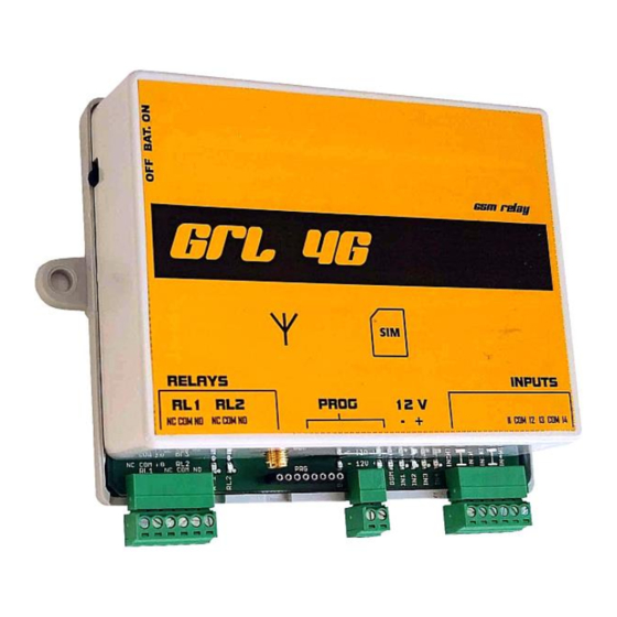
- Page 2 GRL 4G Installation and programming manual v3.1 from fw 204 The device is designed to remotely control 2 separate relays and send notification SMS or call stored voice messages when changing the status of 4 inputs (input on/off).
- Page 3 • After calling the device, you can listen to a voice message with the current status of both relays and all inputs. • Ringing can be used to control relay switching similarly as with the Alphatech GSM Door Intercom or the Alphatech GSM Key devices.
- Page 4 • The device can only be controlled and programmed from the numbers stored on the SIM card which is inside the device. • You can work without or with the PIN code – automatic generation of random PIN code for the inserted SIM card.
- Page 5 Commissioning: • If you wish to program the parameters directly to the SIM card by saving the numbers from any mobile phone, insert that SIM card into this mobile phone and program the SIM card. • Turn off the PIN on the SIM card or set the PIN code to 0000 (see chapter SIM PIN).
- Page 6 SIM PIN If you wish to operate the device with a SIM card without a PIN code, turn off the SIM PIN code (in any type of a mobile phone) before inserting the SIM card into the device. If you wish to operate the device with a SIM card with a PIN code, set the PIN code to 0000 on the SIM card using any type of a mobile phone before inserting the SIM card into the device.
- Page 7 Backup battery switch antenna BAT (green) – indication of battery SIM slot GND+...
- Page 8 Example of wiring: -12V+ Sending SMS SET REL1 ON turns on the light When the level rises, the sensor switches on the IN1 input and the device sends an SMS "P1 closed" (or another agreed SMS – e.g. "The level is above normal"). By sending SMS SET REL2 ON, the pump is switched on.
- Page 9 LED signaling on the GRL4G device Continuous light Continuous light – LED only Blue LED glows/shines (PWR) Continuous light Blinking alternates for 1 sec. ▌▌▌ ▌▌▌...
- Page 10 Programming the GRL4G parameters via SMS text message parameters can For security reasons, GRL only be set from numbers stored on the SIM card under the names ADMIN1 to ADMIN9. SMS messages are always WRITTEN IN LARGE LETTERS Individual SMS elements are always separated by a space (words).
- Page 11 same time, we recommend using SMS for a bulk setup. Using the "READ PAR" SMS, you can first load and read the current values of all parameters into your mobile phone. Use the SMS editor to change the word READ to WRITE in the received SMS and edit the parameter values according to the requirements (rows with parameters that you do not change can be kept or deleted).
- Page 12 0 - disabled 1 - activated WRITE PAR TMGSM:x Set time according to GSM network x: 0 – off 1 - On WRITE PAR WAIT:xx Waiting for the next number in the list to be dialed xx – 10 to 90 seconds (in dozens) WRITE PAR RL1MOD:x Relay mode1 x=0 - SMS control...
- Page 13 xxxx – series of numbers 1234 (see example) if xxxx=# will not call from any input WRITE CALLCLS xxxx Writing of listed inputs, when switched on 1234 it will be called to preset numbers PORTCALL1-7 xxxx – series of numbers 1234 (see example) if xxxx=# will not call from any input WRITE PORTCALL1 yyyy...
- Page 14 no longer possible to program the device remotely (it is necessary to perform a new initialization). INIT – Initialization. During the first setup, when the SIM does not contain any of the ADMINx names, it is necessary to enter such a number on the SIM card using an SMS with the INIT command.
- Page 15 The meaning of the names stored in the SIM card phonebook name Activity PORTOPN1 - sends GRL4G SMS assigned to "INxOPN" when the input state is changed to disconnected (x = 1,2,3,4) PORTOPN2 - sends GRL4G SMS assigned to "INxOPN" when the input state is changed to disconnected (x = 1,2,3,4) PORTOPN3 - sends GRL4G SMS assigned to "INxOPN"...
- Page 16 PORTCALL3 GRL4G calls the number if the number under PORTCALL2 is unavailable, occupied, does not answer the call for a long time - switch relay 1 and relay 2 by ringing - calls are automatically received from the number PORTCALL4 GRL4G calls the number if the number under PORTCALL3 is unavailable, occupied, does not answer the call for a long time...
- Page 17 instructions for your mobile phone). All names listed in the table (PORTOPN PORTCLSx, ADMINx, PARGRL, PARRL1, PARRL2 ...). It must be written in capital letters. There must be no space between names and order numbers (e.g., PORTOPN1).
-
Page 18: Read Status
Examples of SMS communication with GRL4G Example of setting the device name to "demo" WRITE DEVICE demo GRL Response: WRITE DEVICE: OK GRL response to SMS "READ STAT" (DEVICE=demo) READ STATUS: demo: VER: 204 BATTERY:4030mV PWR: 12.3V TIME: 22/12/1 0.14:59 OPER: Vodafone CZ TEMP: 28C IN1: OPEN... - Page 19 WRITE PAR: RL1STAT:2 RL2STAT:2 TIN1:0001 TIN2:0001 TIN3: 0 10 TIN4: 0 20 GRL4G Response: WRITE PAR: TIN1:0001 TIN2:0001 TIN3: 0 10 TIN4: 0 20 Example of SMS for setting GRL4G parameters WRITE PAR: RL1STAT:0 TIN4:0005 Example of CMM for switching REL1 SET REL1 ON GRL4G Response: SET REL1: OK...
- Page 20 text of the programmed notification SMS message is max. 50 characters! Example of sent SMS message when switching on IN1 (default SMS= "Water in container!", name DEVICE= "demo"): demo: Water in a container! Example of setting calls when inputs 1 and 2 are switched on only.
- Page 21 GRL4G with backup battery If you already have purchased a GRL4G with a backup battery, check that the battery switch is in the lower position (switched off) before putting it into operation. Do not store the device with the battery inserted unless the battery switch is in the lower position! Self-discharge may destroy the battery, which is not covered by the manufacturer's warranty.
- Page 22 When the polarity of the battery is rotated, the red LED flashes or lights up. If everything is correct, connect the power supply, and then move the switch to the upper position. – Connect the backup battery to the system. Test the battery backup to function properly by disconnecting the main power supply.
- Page 23 Examples of GRL4G wiring: Contactor connection 1SBE111111R1420 ABB (16 A; 12VAC; 12VDC; NO x2) for heating control – contactor connected to REL2 WRITE PAR RL2MOD:0 230V -12V+ Heating...
- Page 24 Connection of the door lock for opening by ringing from a mobile phone and with the exit button WRITE PAR: RL1MOD:1 RL2MOD:4 Exit button -12V+...
- Page 25 Connection of the motor drive of the gate – ringing (short activation) opens the gate partially (for pedestrians), sending an SMS message opens the gate fully (entrance) WRITE PAR: RL1MOD:1 RL1TMON:02 RL2MOD:0 -24V+ Note: Ringing switches the control on for 2 sec – small opening By sending the SMS SET REL2 ON 0, the control is switched on for 10 sec.
- Page 26 Demonstration example of the GRL4G Master-Slave wiring: According to the level sensor in the water tank on the hill, the pump motor is switched on to the well in the valley (disconnecting the "lower level" contact gives the command to start the pump, switching the contact "upper level"...
- Page 27 https://www.alphatechtechnologies.cz/...
Need help?
Do you have a question about the GRL 4G and is the answer not in the manual?
Questions and answers