Table of Contents
Advertisement
Quick Links
Advertisement
Table of Contents

Summary of Contents for AirDyne AD8
- Page 1 ASSEMBLY MANUAL / OWNER’S MANUAL ASSEMBLY MANUAL / OWNER’S MANUAL...
-
Page 2: Table Of Contents
TABLE OF CONTENTS Important Safety Instructions Using the Machine Safety Warning Labels / Serial Number Locking the Fan Assembly / Storage Power Up / Idle Mode Manual Workout Parts Interval Workouts Hardware Target Workouts Tools Heart Rate Zones Assembly Pausing / Results Mode Moving the Machine Leveling the Machine Maintenance... -
Page 3: Important Safety Instructions
IMPORTANT SAFETY INSTRUCTIONS When using an electrical appliance, basic precautions should always be followed, including the following: This icon means a potentially hazardous situation which, if not avoided, could result in death or serious injury. Obey the following warnings: Read and understand all warnings on this machine. Carefully read and understand the Assembly instructions. - Page 4 Before using this equipment, obey the following warnings: Read and understand the complete Manual. Keep the Manual for future reference. Read and understand all warnings on this machine. If at any time the Warning stickers become loose, unreadable or dislodged, contact your local distributor for replacement stickers. To reduce the risk of electrical shock or unsupervised usage of the equipment, always unplug the power cord from the wall outlet and the machine and wait 5 minutes before cleaning, maintaining or repairing the machine.
-
Page 5: Safety Warning Labels / Serial Number
SAFETY WARNING LABELS AND SERIAL NUMBER • Remove rechargeable batteries from the machine before recharging them. • Do not short-circuit the supply terminals on the batteries. • For safe storage of the machine, remove the batteries and install the Transport and Immobilization Strap to secure the Resistance Fan. - Page 6 SPECIFICATIONS Maximum User Weight: 159 kg (350 lb) Total Surface Area (footprint) of equipment: 9059 cm (1405 in Machine Weight: 51.3 kg (113 lb) Power Requirements: Output Voltage: 9V DC , 1.5A 134.6 cm Optional Batteries: 2 D Batteries (LR20) – not included 53”...
-
Page 7: Parts
PARTS A decal has been applied to all right (“ R ”) and left (“ L ”) parts to assist with assembly. Item Description Item Description Main Assembly Stabilizer, Front Console / Mast Assembly Foot Peg, Right Seat Pedal, Right Handlebar, Left Handlebar, Right Foot Peg, Left... -
Page 8: Hardware
HARDWARE / TOOLS Item Description Item Description Lock Washer, M8 Flat Washer, M8 Note: Selected pieces of Hardware have been provided as spares on the Hardware Card. Be aware that there may be remaining Hardware after the proper assembly of your machine. Tools Included 13 / 15 mm... -
Page 9: Assembly
ASSEMBLY 1. Attach Stabilizers to Frame Assembly 2. Attach Pedals to Frame Assembly If the threads strip due to improper installation, then the Pedals can disengage from the bike and/or break while under usage, which can result in serious injury to the user. Note: The Left Pedal is reverse-threaded. - Page 10 3. Connect Cables and Attach the Console/Mast Assembly to Frame Assembly NOTICE: Do not pinch or cut the cables.
- Page 11 4. Attach Handlebar Arms to Frame Assembly NOTICE: Remove tag from the Handlebar Arm. Align the open curve (a) on the handlebar with the smooth curve (1a) on the force or hammer into position. Gently rock the handlebar forward and backward to make sure it is fully seated on the shaft.
- Page 12 5. Assemble Foot Pegs and Hardware, and Attach Foot Pegs to Frame Assembly NOTICE: Push the Shoulder Screw (F) completely through the Foot Peg, and press the Washer (E) tightly onto the end of the Foot Peg. Be sure the Washer does not touch the screw threads (F1). Do not let the Washer fall off the Foot Peg during installation.
- Page 13 6. Attach Seat to Seat Post NOTICE: Be sure the Seat is straight and level. Tighten both nuts (3b) on the Seat bracket (3a) to hold the Seat in position.
- Page 14 7. Connect Power Adapter The console for your machine can operate on battery power or AC power. If batteries and the Power Adapter are installed, the console will use the Power Adapter to operate. Note: If you use rechargeable batteries, the Power Adapter will not recharge the batteries.
-
Page 15: Moving The Machine
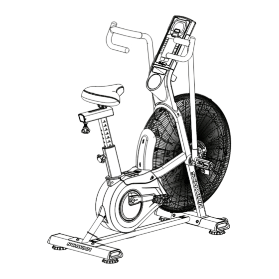
BEFORE YOU START Moving the Machine The machine may be moved by one or more persons depending on their physical abilities and capacities. precautions and lifting techniques. Remove the power adapter. Secure the Crank Arm to the Seat Post with the Transport and Immobilization Strap (T). - Page 16 Transport and Immobilization Strap Seat Slider Adjustment Knob Stabilizer, Front Power adapter Seat Post Adjustment Knob Foot Peg AirDyne Air Diverter ™ Foot Step Pad Air Resistance Fan Pedal Battery Compartment WARNING! Use the values calculated or measured by the machine’s computer for reference purposes only. The heart rate displayed is an approximation and should be used for reference only.
-
Page 17: Console Features
Console Features The Console provides information about your workout on the display screens. Tachometer Display Programs • Manual Program • 20/10 Interval Data Display • 30/90 Interval Keypad • Custom Interval • Time Target • Heart Rate Zones • Calorie Target •... - Page 18 Program Data Display TIME workout, it shows the remaining time. During workout summary it shows the total time. 7. ROUND segment shows the number of the current round. The second 00 seg- is 49. 8. TIME/INTERVAL area The Sprint and Recover labels are enabled for Interval programs only. Default mode shows lapsed or remaining time, depending on the pro- time).
-
Page 19: Remote Heart Rate Monitor
Keypad Functions RATE SELECT button- Cycles through the Tach metric display options (CAL/MIN, WATTS, RPM, SPEED). Push and hold the button for 3 seconds to go to SCAN mode and cycle through the rates automatically. Each rate is displayed for 3 seconds. 20/10 INTERVAL button- Selects the 20/10 Interval workout. -
Page 20: Auto-Calibration
patible model. (Coded POLAR ® heart rate straps such as POLAR ® OwnCode ® chest straps will not work with this equipment.) If you have a pacemaker or other implanted electronic device, consult your doctor before using a wireless chest strap or other telemetric heart rate monitor. Heart Rate Calculations BPM, where as highly trained runners may have readings of 40 BPM or lower. -
Page 21: Operations
OPERATION What to Wear How Often Should You Exercise Consult a physician before you start an exercise program. Stop exercising if you feel pain or tightness in your chest, become short of breath, or feel faint. Contact your doctor before you use the machine again. Use the values calculated or measured by the machine’s computer for reference purposes only. -
Page 22: Locking The Fan Assembly / Storage
When done with your workout, reduce the Resistance Fan speed until the machine fully stops. This bike cannot stop the Pedals independently of the Resistance Fan. Reduce the pace to slow the Resistance Fan and Pedals to a stop. Do not dismount the bike until the Pedals have come to a complete stop. -
Page 23: Interval Workouts
20/10 Interval Workout The Console allows you to select an Interval workout of 20 seconds Sprint followed by 10 seconds Recover (1 round).The default number of rounds is 8 rounds (total time - 4 minutes). 1. Sit on the machine. 2. - Page 24 4. Push the START/RESUME button to start the timer, and start to pedal. Calories Target Workout The Console allows you to select a Calories Target workout and enter your own Calories value. The default value is 100 calories. 1. Sit on the machine. adjust in 25 calorie increments.
-
Page 25: Heart Rate Zones
Heart Rate Zones The Console allows you to set your Heart Rate Zones and use the calculated values to monitor your workout intensity. This feature can be used in conjunction with all of the other programs. 1. Sit on the machine. 2. - Page 26 CONSOLE SERVICE MODE Manual and Target Programs Interval Programs The Heart Rate area cycles the Average HR and MAX HR values. If HR Zones were calculated for the program, the values are displayed. The Results display will show for 5 minutes and then reset. Push STOP/RESET to stop the Results display and go back to Idle Mode.
-
Page 27: Maintenance
MAINTENANCE Read all maintenance instructions fully before you start any repair work. In some conditions, an assistant is required to do the necessary tasks. Equipment must be regularly examined for damage and repairs. The owner is responsible to make sure that regular maintenance is done. -
Page 28: Replacing The Console Batteries
Replacing the Console Batteries The Console will display the Battery Indicator icon when the batteries are around 25% of their rated power during power up. If you use rechargeable batteries, the optional power adapter will not recharge the batteries. To open the battery bay, loosen the preinstalled screw in the cover. When replacing the batteries, make sure the batteries point in the +/- direction shown in the battery bay. -
Page 29: Maintenance Parts
QQ Drive Pulley Foot Peg, Right Foot Peg, Left Drive Belt Pedal, Right Strap, Transport/Immobilization Crank Link Assembly Crank Arm, Right Data Cable, Upper Power Adapter Shroud, Right Power Wire, Upper AirDyne Air Diverter ™ Stabilizer, Rear Data Cable, Lower... -
Page 30: Troubleshooting
TROUBLESHOOTING Condition/Problem Things to Check Solution Console will not power up/ If bike has AC adapter, Make sure unit is plugged into a functioning wall outlet. turn on/start check electrical (wall) outlet If bike has AC adapter, Connection should be secure and undamaged. Replace check connection at unit adapter or connection at unit if either are damaged. - Page 31 Condition/Problem Things to Check Solution Check data cable integrity All wires in the cable should be intact. If any are cut or crimped, sleep mode) while in use replace cable. Check data cable Be sure cable is connected securely and oriented properly. connections/orientation Small latch on connector should line up and snap into place.
- Page 32 ™ ™ ™ ™ ™ ™ 8007518.011523.K...
Need help?
Do you have a question about the AD8 and is the answer not in the manual?
Questions and answers