Table of Contents
Advertisement
Quick Links
Advertisement
Table of Contents

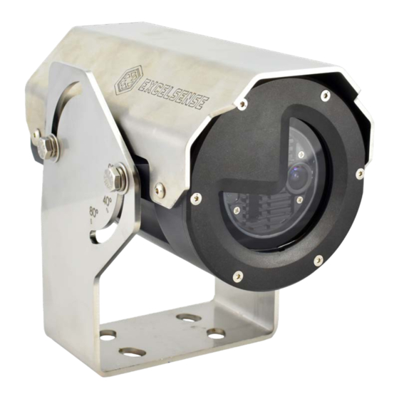
Summary of Contents for EXCELSENSE ToughEye-1700
- Page 1 ToughEye-1700™ User Manual, V1.3...
-
Page 2: Table Of Contents
Self-Cleaning Trigger Button Box Video Monitor Kits 7” Standard Series 4ch Monitor Kit [AM-4C-7IN-S] 7” Extreme Series 4ch Monitor Kit [AM-4C-7IN-X] Mounting Accessories ToughEye-1700™ Standard Bracket Field Welding Bracket Options System Installation Configuration Selection IP Camera Configurations Network Configuration A-1 Option 1 For more information, please contact info@excelsensetechnologies.com or 1-800-914-3193... - Page 3 Triggering the ToughEye-1700™ Manual Trigger Manual Trigger when using PoE+ Remote Manual Trigger using Web Interface Manual Trigger using External Button Automatic Trigger ToughEye-1700™ Controller Module Communication Technical Information ToughEye-1700™ Thermal Variants Standard-Thermal Variant Integrated High-Power LED Variant Background LED Illumination Control...
-
Page 4: Overview
(e.g. LLDP, CDP, etc.) communications disabled on the port, which should be preset to deliver up to 30W of guaranteed power. Failure to meet these requirements may cause faults that can lead to permanent damage to the ToughEye-1700™’s internal electronics. -
Page 5: Caution
7. Do not attempt to disassemble ToughEye-1700™ in order to access internal components. Consult ExcelSense for technical support as required. 8. Never face the ToughEye-1700™ directly towards the sun or any bright or reflective light, which may cause smear on the picture and possible damage to the CCD. -
Page 6: Compliance
Compliance Electromagnetic Compliance Information The ToughEye-1700™ and its custom peripheral hardware, produced and sold by ExcelSense Technologies, have been tested and found to comply with the applicable regulatory requirements and limits for electromagnetic compatibility (EMC) for a Class A device, pursuant to part 15 of the FCC Rules. -
Page 7: Specifications
(DC port) Input Voltage, V (PoE+ port) ToughEye-1700™ utilizes a hardware-layer PoE+ classification protocol. It is not compatible with any software-layer protocols, such as LLDP or CDP. PoE+ V is 42.5V at the camera, as per IEEE802.3at. The camera will engage its PoE undervoltage IN (min) protection at 36V. - Page 8 Power Consumption, P 5W (Idle) 25W (Heating) Input Protection (DC port) Clamping Voltage, V 116V Peak-pulse Power, P 6.4kW (28ms pulse duration) Peak-pulse Current, I Overvoltage Lockout, V OVLO Engage lockout (rising) 33.3V Disengage lockout (falling) 33.0V Undervoltage Lockout, V UVLO Engage lockout (falling) 17.0V...
-
Page 9: Ordering Options
Ordering Options TE17 - ToughEye-1700™ camera Lens Angle (customization available) 080 - Approx. 80° Horizontal FoV 100 - Approx. 100° Horizontal FoV Temperature Rating Environmental Resistance X - Extreme: -40 C to 60 S - Standard Corrosion Resistant C - Highly Corrosion Resistant... -
Page 10: Accessories
Accessories The following lists the standard accessories available for ToughEye-1700™ installations. Cable Harnesses Part Number Guide For more information, please contact info@excelsensetechnologies.com or 1-800-914-3193... -
Page 11: Cables List
Cables List The following table lists standard cables available. If a variant is required that cannot be found in this table, please contact an ExcelSense representative. For more detailed information on a particular cable, please reach out to info@excelsensetechnologies.com. For more information, please contact info@excelsensetechnologies.com or 1-800-914-3193... - Page 12 For more information, please contact info@excelsensetechnologies.com or 1-800-914-3193...
-
Page 13: Cable Accessory Detail - Sealed Inline Rj45 Coupler
[AC17-RJ45] to achieve an IP67 dust/water rated, network cable connection. Power Supplies DC Source - 24VDC Supply In applications where only AC power is available, the following AC-DC converter can be used to supply the ToughEye-1700™ and optionally an external monitor with 24VDC. Part Description Preview... -
Page 14: Poe+ Source - Ieee802.At Compliant Pse
In applications where the PoE+ power method is preferred, it is important to ensure the correct PoE power source equipment (PSE) class level is selected. The ToughEye-1700™ is a class 4 powered device (PD), meaning it is rated to draw up to 25.5W, as per the IEEE802.at standard. -
Page 15: Junction Boxes
Self-Cleaning Trigger Button Box The ToughEye-1700™ can be triggered to clean its lens through many different ways, one of them being through the hardware trigger method. This method involves accessing the trigger, power, and ground signals of the electrical system in order to switch the trigger signal. -
Page 16: Video Monitor Kits
The following accessories are available for mounting the ToughEye-1700™. ToughEye-1700™ Standard Bracket The ToughEye-1700™ Standard Bracket is included as it is the default bracket in most ToughEye-1700™ installations. The bracket should first be mounted to a suitable horizontal support with sufficient strength. The camera ships with high strength, 3/8”-16, 1.25”... - Page 17 Mounting pattern and bolt details If the camera is mounted to a vertical surface a horizontal bracket [MB-TE-WB] can first be welded to the vertical surface, in order to provide a suitable mounting point. With the bracket mounted the camera can be installed. Start by placing the camera within the bracket and loosely attaching it at all 4 mounting points.
-
Page 18: Field Welding Bracket Options
Field Welding Bracket Damping Kit, ToughEye Compatible. Suitable for welding to existing horizontal or vertical surfaces in high-vibration applications. The image below shows the MB-TE-DW-K kit with the standard ToughEye-1700™ bracket installed. For more information, please contact info@excelsensetechnologies.com or 1-800-914-3193... -
Page 19: System Installation
Configuration A-1 It is important to note that IP video has inherent latency due to video compression. The ToughEye-1700™ latency is tested at approximately 150ms , so only in applications where this latency can be tolerated is the network stream recommended. - Page 20 Cat-5e adapter. For details on usage of the Cat-5e adapter please refer to section Sealed In-line RJ45 Coupler. 3. The RJ45 Adapter Cable [AC17-RJ45] can now be plugged into the ToughEye-1700™ camera. For more information, please contact info@excelsensetechnologies.com or 1-800-914-3193...
-
Page 21: Network Configuration
Refer to the Triggering the ToughEye-1700™ section for triggering details. ● Route the main cable to the ToughEye-1700™ camera, or to an optional extension cable. If an extension cable is used, it should be connected in-line between the main cable and the camera. -
Page 22: Analog Camera Configurations
Configuration B-2 Analog Configuration B-1 The monitor can be integrated into the ToughEye-1700™ analog camera system using the Standard Boost Box. This installation is recommended for applications requiring rugged, IP6x cables and connections. The monitor, however, should be mounted in an enclosed, protected environment. -
Page 23: Analog Configuration
6. If a camera extension cable was used, connect the main cable to the extension cable. If not, connect the main cable to the ToughEye-1700™ directly. Route the main cable from the ToughEye-1700™ to the junction box through the camera port gland. Properly tighten the gland using a wrench to achieve an IP67-rated seal at the interface. - Page 24 7. With the power off, safely connect all power and trigger wires to their respective sources as shown above. Refer to the Triggering the ToughEye-1700™ section for detailed self-clean triggering instructions. 8. The ToughEye-1700™’s composite (CVBS) analog stream can be interfaced through the 75Ω...
-
Page 25: Interfacing The Tougheye-1700
Interfacing the ToughEye-1700™ Powering the ToughEye-1700™ Important Note: As per rule 2-024(2) of the Canadian Electrical Code Part I, ToughEye-1700 does not require approval in order to be installed. However, it must be connected to a Class 2 output, as permitted by the Canadian Electrical Code Part I. (See rule 16-222 and relevant appendices). -
Page 26: Dc Power Source
Cabling details are available in the Accessories and Cable Drawings sections of this document. For installations where the ToughEye-1700™ is powered directly by a battery, to prevent an overcurrent event caused by potential cable damage, a 2A fast-blow external in-line fuse is recommended to be used between the ToughEye-1700™... -
Page 27: Triggering The Tougheye-1700
Triggering the ToughEye-1700™ The ToughEye-1700™ performs cleaning cycles in response to a trigger event. The triggering event method is an important consideration at the time of specifying your system topology. The decision is based on many factors, including availability of a digital switch, remote triggering requirements, and the general nature of the application. -
Page 28: Manual Trigger When Using Poe
Manual Trigger when using PoE+ The manual trigger method can also be used when the ToughEye-1700™ is powered with PoE+. To access the necessary signal wires, a compatible MC17-series main cable must be used. First ensure that the external trigger signal’s reference level is the same as the camera’s. This can be done by tying the trigger’s reference signal to one of the black wires labelled “GND”... -
Page 29: Manual Trigger Using External Button
In this wiring configuration, the ToughEye-1700™ performs a cleaning cycle when the reverse gear is engaged (rising edge where TRIG goes from low to high). When the reverse gear is disengaged, the TRIG signal goes back to 0V and the device trigger is reset, and ready to activate a subsequent cleaning cycle upon another rising edge. -
Page 30: Tougheye-1700™ Controller Module Communication
ToughEye-1700™ Controller Module Communication The ToughEye-1700™ controller module uses the serial RS-232 protocol to communicate with custom light-weight ExcelSense applications. These applications can be used to retrieve cleaning cycle data or update the controller firmware. The programming adapter [PA-TE17-USB], which breaks out a USB connection to the client-side PC, is connected in-line between the ToughEye-1700™... -
Page 31: Technical Information
7°C. LED Illumination Control Integrated light variants of ToughEye-1700™ are designed to eliminate the risks of thermal runaway by utilizing their automatic active illumination control. This closed-loop control feature ensures that regardless of the ambient thermal conditions, the device will operate its LEDs in a thermally stable manner. -
Page 32: Specifications
Specifications Active Illumination Control Curves The active illumination control curves illustrate how the device will operate its integrated LEDs given the ambient thermal conditions. The figures below are based on empirical data in a controlled thermal environment, where the device was operated in the absence of direct solar loading. -
Page 33: Spectral Distribution
Spectral Distribution The device operates two integrated LED chipsets at a correlated colour temperature (CCT) of 4000K. The red plot in the figure below illustrates the spectral distribution of the LEDs. Radiation Pattern Characteristization The following figures are typical radiation patterns at full load, ambient temperature of 20°C, measured in a dark environment at a distance of 30cm. -
Page 34: Optical Module - Network Interface
Optical Module - Network Interface The configuration and operation of the optical module’s network interface may vary depending on the specific application. Before accessing the web interface of the camera, please refer to the Optical Module Web Interface Manual, found here, for detailed information as well as step-by-step instructions on how to operate the optical module. -
Page 35: Tougheye-1700™ Dimensions
ToughEye-1700™ Dimensions ToughEye-1700™ Mechanical Dimensions For more information, please contact info@excelsensetechnologies.com or 1-800-914-3193...
Need help?
Do you have a question about the ToughEye-1700 and is the answer not in the manual?
Questions and answers