Table of Contents
Advertisement
Quick Links
Remote I/O R7K4F Series
MECHATROLINK I/O MODULE
(NPN/PNP discrete input, 32 points, screw terminal block,
MECHATROLINK- I/- II use)
Functions & Features
• 32 points NPN/PNP discrete input module for
MECHATROLINK- I/- II
210 [8.27]
MODEL: R7K4FML-6-DA32-R[1]
ORDERING INFORMATION
• Code number: R7K4FML-6-DA32-R[1]
Specify a code from below for [1].
(e.g. R7K4FML-6-DA32-R/Q)
• Specify the specification for option code /Q
(e.g. /C01)
TERMINAL BLOCK
6: Screw terminal block for power supply
Connector for MECHATROLINK-I/-II
Screw terminal block for I/O
I/O TYPE
DA32: NPN/PNP discrete input, 32 points
POWER INPUT
DC power
R: 24 V DC
(Operational voltage range: ±10 %; ripple 10 %p-p max.)
[1] OPTIONS
blank: none
/Q: With options (specify the specification)
https://www.m-system.co.jp/
53.5
[2.11]
47 [1.85]
mm [inch]
R7K4FML-6-DA32 SPECIFICATIONS
MODEL: R7K4FML-6-DA32
SPECIFICATIONS OF OPTION: Q
COATING (For the detail, refer to M-System's web site.)
/C01: Silicone coating
/C02: Polyurethane coating
/C03: Rubber coating
GENERAL SPECIFICATIONS
Connection
MECHATROLINK: MECHATROLINK-I/-II connector
Power input, input: M3 separable screw terminal (torque
0.5 N·m)
Solderless terminal: Refer to the drawing at the end of the
section.
Recommended manufacturer: Japan Solderless Terminal
MFG.Co.Ltd, Nichifu Co.,ltd
Applicable wire size: 0.25 to 1.65 mm
Screw terminal: Nickel-plated steel
Housing material: Flame-resistant resin (gray)
Isolation: Input to MECHATROLINK or FE to power
Status indicator LED: PWR, ERR, SD, RD
(Refer to the instruction manual for details)
Discrete input status indicator LED: Green LED turns on with
input ON
■Recommended solderless terminal
3.3 [.13] max
MECHATROLINK COMMUNICATION
MECHATROLINK mode: Set with DIP switches
(MECHATROLINK-I or -II, data length; Factory setting:
MECHATROLINK-II; data length (32 byte)
(Refer to the instruction manual)
Station address: 60H - 7FH
(Function selected with Rotary SW. Factory setting: 61H).
(Refer to the instruction manual)
■ MECHATROLINK-I
Baud rate: 4 Mbps
Transmission distance: 50 m max.
Distance between stations: 30 cm min.
Transmission media: MECHATROLINK cable (Model JEPMC-
W6003-x-E, Yaskawa Controls Co., Ltd.)
Max. number of slaves: 15
(The maximum number of slaves might change depending
on the master unit. Refer to the manual of the master unit)
Transmission cycle: 2 msec. (fixed)
Data length: 17 byte
2
(AWG 22 to 16)
mm [inch]
ES-7771-A Rev.1 Page 1/8
Advertisement
Table of Contents

Related Manuals for M-system R7K4F Series


Summary of Contents for M-system R7K4F Series
- Page 1 MODEL: R7K4FML-6-DA32 Remote I/O R7K4F Series SPECIFICATIONS OF OPTION: Q COATING (For the detail, refer to M-System's web site.) /C01: Silicone coating MECHATROLINK I/O MODULE /C02: Polyurethane coating (NPN/PNP discrete input, 32 points, screw terminal block, /C03: Rubber coating MECHATROLINK- I/- II use) Functions &...
-
Page 2: Input Specifications
Dielectric strength: 1500 V AC @ 1 minute (input to power) 500 V AC @ 1 minute (MECHATROLINK or FE to input or power) STANDARDS & APPROVALS EU conformity: EMC Directive EMI EN 61000-6-4 EMS EN 61000-6-2 RoHS Directive R7K4FML-6-DA32 SPECIFICATIONS ES-7771-A Rev.1 Page 2/8 https://www.m-system.co.jp/... -
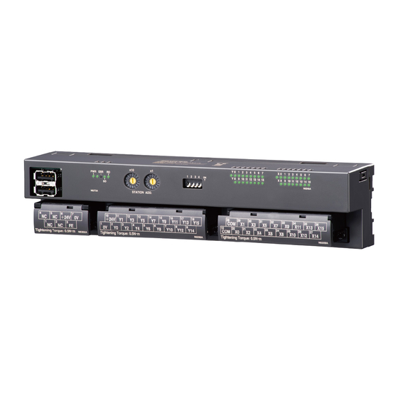
Page 3: External View
Be sure to connect the terminating resistors to the unit at both ends of transmission line. Use the terminating resistor dedicated for MECHATROLINK: Model JEPMC-W6022, Yaskawa Controls Co., Ltd. Certain types of Master units may have incorporated terminating resistors. Consult the instruction manual of the Master unit. R7K4FML-6-DA32 SPECIFICATIONS ES-7771-A Rev.1 Page 3/8 https://www.m-system.co.jp/... - Page 4 Out Data: Highest In Data: Highest Byte 17 through 31 are unavailable for MECHATROLINK-I and MECHATROLINK-II in the 17-byte mode. (Only available for MECHATROLINK-II in the 32-byte mode) (Out Data: Highest) (In Data: Highest) R7K4FML-6-DA32 SPECIFICATIONS ES-7771-A Rev.1 Page 4/8 https://www.m-system.co.jp/...
- Page 5 47 [1.85] 210 [8.27] 45 [1.77] DIN RAIL 35mm wide (4 [.16]) 2 - 4.3 dia. 4 deep [2 - 1.17 dia. 7−M3 SCREW 36−M3 SCREW .16 deep] TERMINALS FOR POWER TERMINALS FOR INPUT R7K4FML-6-DA32 SPECIFICATIONS ES-7771-A Rev.1 Page 5/8 https://www.m-system.co.jp/...
- Page 6 MODEL: R7K4FML-6-DA32 MOUNTING REQUIREMENTS unit: mm [inch] 220 [8.66] 2–M4 R7K4FML-6-DA32 SPECIFICATIONS ES-7771-A Rev.1 Page 6/8 https://www.m-system.co.jp/...
- Page 7 Comm Circuit Control Circuit ■ Input Connection Examples PNP Connection 24V DC – Control Circuit NPN Connection – + *MECHATROLINK connectors are internally connected. The network cable can be connected to either one. R7K4FML-6-DA32 SPECIFICATIONS ES-7771-A Rev.1 Page 7/8 https://www.m-system.co.jp/...
- Page 8 MODEL: R7K4FML-6-DA32 Specifications are subject to change without notice. R7K4FML-6-DA32 SPECIFICATIONS ES-7771-A Rev.1 Page 8/8 https://www.m-system.co.jp/...
Need help?
Do you have a question about the R7K4F Series and is the answer not in the manual?
Questions and answers