
Related Manuals for Clarion MSS433

Summary of Contents for Clarion MSS433
- Page 1 SOURCE COMMANDER MSS433 M U L T I S T A T I O N A/V SELECTOR O W N E R ’ S M A N U A L INSTALLATION GUIDE...
-
Page 2: Table Of Contents
Troubleshooting ............19 dures. Even though this manual provides general installation and operation instructions for your new Clarion MSS433 Specifications ............20 Multistation A/V Selector, it does not show the exact installa- tion methods for your particular vehicle. -
Page 3: Introduction
SOURCE COMMANDER MSS433 About The Manual And Warranty NTRODUCTION To start enjoying your new Clarion MSS433 Multistation A/V The Clarion MSS433 is a full-featured Multistation A/V Selector, please read all remaining instructions listed in this Selector specifically created for the mobile environment. -
Page 4: Installation And Operation Precautions
DOING SO WILL VOID THE WARRANTY. any holes or installing any screws. • Do not place heavy objects on the MSS433 Multistation • Always wear protective eyewear when using tools. A/V Selector or Control Station(s). - Page 5 SOURCE COMMANDER MSS433 • Do not drop or excessively jar the MSS433 Multistation A/V Selector or Control Station(s). • Do not use liquid cleaners on any surfaces. Only use a soft (cotton or other non-static) cloth to wipe off finger- prints or other imprints from the faceplate or remote con- trol.
-
Page 6: Installation And Wiring
OWNER’S MANUAL/INSTALLATION GUIDE Installing the MSS433 NSTALLATION IRING Parts List • (1) Source Commander MSS433 A/V Selector M4 x 15 Self-tapping Sheet Metal Screw (4 supplied) • (3) Control Stations • (3) Control Station Cables • (2) Mounting L-Brackets • (4) M4 x 8 Pan Head Machine Screws •... - Page 7 SOURCE COMMANDER MSS433 Installing the Control Station MSS433 Wiring for the 4-Pin Power Harness Fuse (Not Supplied) Yellow Ignition Switch Reverse Switch Battery Green Black Reverse Lights (on vehicle’s rear) To Ground To Vehicle Circuits Reverse (Green) Ignition (Red) Opening...
- Page 8 OWNER’S MANUAL/INSTALLATION GUIDE MSS433 Wiring for VCR NSTALLATION IRING ONTINUED MSS433 Wiring for DVD Disc Player Videocassette Recorder (rear view) Yellow Figure 5. Wiring diagram for a VCR Input. Figure 4. Wiring diagram using a VS718 DVD player.
- Page 9 SOURCE COMMANDER MSS433 MSS433 Wiring for Rear Vision Camera Figure 6. Wiring diagram for a Clarion Rear Vision Camera.
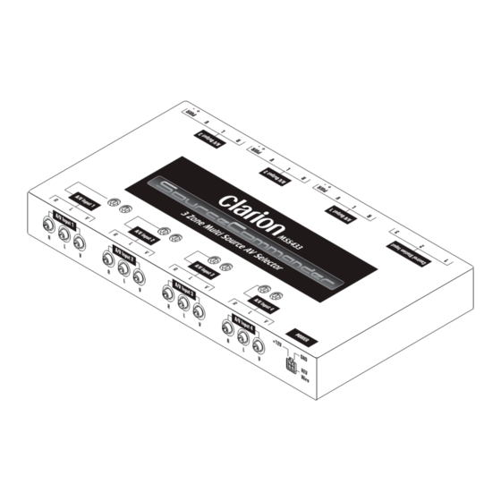
- Page 10 2-Pin Connector Positive Lead (Male Pins) Chassis Reverse (Green) View Negative Lead Ignition (Red) Chassis Positive Lead View Ground (Black) Battery (Yellow) Figure 7. 4- and 2-pin Molex Power connector pinouts. Figure 8. MSS433 Chassis A/V Inputs, Outputs, & Power connectors.
-
Page 11: Description Of Mss433 Front Connectors
(e.g., Clarion CVP9700 VCR, VS718 DVD Player, etc.) A/V INPUT 2 (3 -RCA Jacks) to the MSS433 A/V Selector. See Applications on page Same as A/V Input 1. Use these jacks to connect a second video source (e.g., video game console, etc.) - Page 12 Same as A/V Input 1. Use these jacks to connect a fourth video source. NOTE: When using a optional Clarion Rear Vision Camera, the video connection must be connected to A/V Input 4 to function properly with the reverse wire. See Figure 6 on page 8 for connection configuration.
-
Page 13: Description Of Mss433 Rear Connectors
The Control Station connected to this port provides control and selection of Zone 1 audio/video sources. A/V OUTPUT 1 (3 -RCA Jacks) Use this output when connecting the MSS433 to an exter- CONTROL STATION 2 (6 -Pin Connector) nal (PAL/NTSC-compatible type) video monitor for Zone The Control Station connected to this port provides control and selection of Zone 2 audio/video sources. -
Page 14: Description Of Control Station
ONTROL TATION A/V OUTPUT 2 (3 -RCA Jacks) Use this output when connecting the MSS433 to an exter- nal video monitor for Zone 2. MONITOR 2 OUTPUT (2 -Pin Connector) Connect to the monitor’s +12 V and ground for Zone 2. - Page 15 (see page 6 for intallation informa- POWER Button tion). When ignition is applied to the MSS433’s ignition lead, all control stations are automatically set into the Stand-By mode (no power output from the monitor’s power con- nector). Press the POWER button on any Control Station and the source LED will illuminate and the monitor will power on.
-
Page 16: Applications Input Configurations
OWNER’S MANUAL/INSTALLATION GUIDE PPLICATIONS NPUT ONFIGURATIONS YELLOW-Battery(+12V ) Battery (+12) GREEN-Reverse Rear Vision Camera To Reverse Wire Back-up Light (optional) VS718 CVP9700 Video Game etc. Figure 12. Using the MSS433 Input Connectors. -
Page 17: Applications Output Configurations
SOURCE COMMANDER MSS433 PPLICATIONS UTPUT ONFIGURATIONS VMA7192 IR to TTX001 Control Station 3 VMA7192 IR to VDH910 Control Station 2 WH200 IR HEADPHONES Control Station 1 VRX918R CCA-389 (optional) Figure 13. Using the MSS433 Output Connectors. -
Page 18: Operating The Mss433
The Rear Vision Camera’s video output from the CAA188 must be connected directly to A/V Input 4 Viewing A Video Game (If Installed) only. (see MSS433 Wiring for Rear Vision Camera on 1. After system and individual control station power is on, page 8) power on the video game player and insert a desired game cartridge. - Page 19 SOURCE COMMANDER MSS433 video game source input. Its TV monitor should now dis- play the selected source. 3. Adjust the audio system’s volume control to a desired lis- tening level. Viewing A DVD (VS718) 1. After system and individual control station power is on, insert a DVD in the DVD player and press PLAY on the corresponding IR Remote Control.
-
Page 20: Troubleshooting
No Ignition power Check for +12 V on Ignition lead connected. to +12V source when vehicle ination on the to MSS433. If voltage is low, use shifted into reverse. Control Station. relay circuit. Camera not connected Connect a Clarion Rear Vision Station DIN not Properly connect to MSS433;... -
Page 21: Specifications
1.9 x 2.8 in. (48 x 72 mm) Input Impedance: 82k Ohms Due to Clarion’s ongoing research and development, the product specifications and appearances Input/Output Gain: 0dB +/-2dB at Max volume with listed in this manual are subject to change without prior notice. - Page 22 Clarion Co., Ltd. ©2001 Clarion 80-00433-GK 2001-MSS433-10 Rev. 1 (08/01)
Need help?
Do you have a question about the MSS433 and is the answer not in the manual?
Questions and answers