Table of Contents
Advertisement
Quick Links
www.ti.com
Design Guide:
Automotive, High-Power, High-Performance SiC Traction
Inverter Reference Design
Description
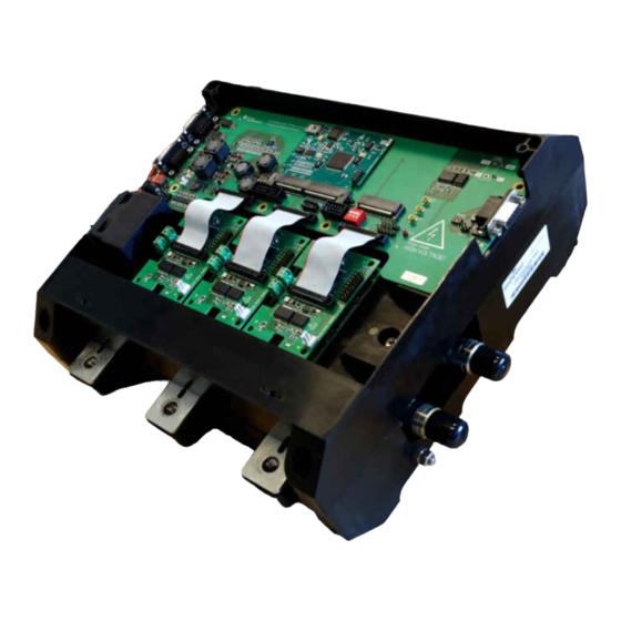
TIDM-2014 is a 800-V, 300 kW SiC-based traction
inverter system reference design developed by
Texas Instruments and Wolfspeed which provides
a foundation for design engineers to create high-
performance, high-efficiency traction inverter systems
and get to market faster. The design features
high-performance isolated gate driver with real-time
variable gate drive strength, isolated bias supply with
integrated transformer along with TI's high real-time
performance, MCUs that can control traction motor
even at speeds greater than 20,000 RPM while
supporting functional safety requirements.
Resources
TIDM-02014
UCC5880-Q1,
AM2634-Q1
TMS320F280039C-Q1,
UCC14240-Q1
UCC12051-Q1,
AMC3330-Q1
TCAN1462-Q1, ISO1042-Q1,
ALM2403-Q1
Ask our TI E2E
12 V Battery Vin
Supply
Diagnostics /
Bias Supply High Side
Monitoring
Batt Volt
Monitoring
Supply
Diagnostics /
Bias Supply Low Side
Monitoring
PMIC
VCU
SPI
ASC
WD
BIST
CAN
VCU
PWM
PWM
HSM
CLB
SPI / Fault
SPI
SPI
Sensing and gate driver
diagnostics
CMPSS
Sensing signal
Isolated Amplifier
ADC
Isolated Comparator
Wired
VCU
Interface
Excitation & Feedback
ADC
Safety MCU
TIDUF23 – MAY 2023
Submit Document Feedback
Design Folder
Product Folder
Product Folder
Product Folder
Product Folder
™
support experts
800 V Bus
DC Link Cap
Discharge
Motor Phases
DESAT
OUT1
Adj.
M
Gate
OUT2
SiC
drive
Power Modules
Isolated
NTC
Gate Driver
Hall
Temp
R
A to D
Sensing
Resolver
A to D
Temp Sensing
/ Hall
ASC
Phase Node sensing
Phase Current Sensing
DC Bus Sensing
DC Bus
Resolver AFE
Excitation
Signal Conditioning
Copyright © 2023 Texas Instruments Incorporated
Features
•
Real-time variable gate drive strength features
enable improvement in system efficiency by
minimizing the SiC switching power losses and
accurate bias supply minimizes conductive losses .
•
Isolated gate drivers and bias supply module
reduce PCB area by 30%.
•
High performance MCUs enable industry's fastest
motor control loop (<2 µs), which helps to minimize
torque ripple and provides smooth speed and
torque current profiles to the traction motor.
•
UCC5880-Q1 and AM2634-Q1 are Functional
Safety-Compliant targeted devices.
•
Enhance system reliability with reinforced rated
capacitive isolation technology and early failure
detection.
Applications
•
HEV/EV Traction Inverters
Automotive, High-Power, High-Performance SiC Traction Inverter Reference
Description
1
Design
Advertisement
Table of Contents

Related Manuals for Texas Instruments TIDM-2014

Summary of Contents for Texas Instruments TIDM-2014
- Page 1 Design Guide: Automotive, High-Power, High-Performance SiC Traction Inverter Reference Design Description Features TIDM-2014 is a 800-V, 300 kW SiC-based traction • Real-time variable gate drive strength features inverter system reference design developed by enable improvement in system efficiency by Texas Instruments and Wolfspeed which provides...
-
Page 2: System Description
CAUTION Do not leave the design powered when unattended. Automotive, High-Power, High-Performance SiC Traction Inverter Reference TIDUF23 – MAY 2023 Design Submit Document Feedback Copyright © 2023 Texas Instruments Incorporated... - Page 3 The included current sensor board uses the LEM 510-S. Please refer to the LF 510-S data sheet provided LEM USA Inc. for more detailed information. TIDUF23 – MAY 2023 Automotive, High-Power, High-Performance SiC Traction Inverter Reference Submit Document Feedback Design Copyright © 2023 Texas Instruments Incorporated...
- Page 4 Resolver AFE Interface Excitation Excitation & Feedback Signal Conditioning Safety MCU Figure 2-1. TIDM-02014 SiC Inverter System Block Diagram Automotive, High-Power, High-Performance SiC Traction Inverter Reference TIDUF23 – MAY 2023 Design Submit Document Feedback Copyright © 2023 Texas Instruments Incorporated...
-
Page 5: Design Considerations
32.25 kW/L which is more than 2x comparable Silicon (Si) based inverters. 2.3 Highlighted Products This reference design features the following Texas Instruments devices. 2.3.1 UCC5880-Q1 The UCC5880-Q1 is a functional safety compliant isolated gate driver targeted for EV/HEV traction inverter applications. - Page 6 While the ISO1042-Q1 device is available for both basic and reinforced isolation, this reference design uses the device featuring reinforced isolation. Automotive, High-Power, High-Performance SiC Traction Inverter Reference TIDUF23 – MAY 2023 Design Submit Document Feedback Copyright © 2023 Texas Instruments Incorporated...
- Page 7 However,note that several resistors on the control need to be populated or depopulated when switching between the control cards. The details of the resistor changes are provided in Section 3.1. TIDUF23 – MAY 2023 Automotive, High-Power, High-Performance SiC Traction Inverter Reference Submit Document Feedback Design Copyright © 2023 Texas Instruments Incorporated...
- Page 8 AM263x MCUs. Figure 2-3. AM263x Sitara™ Control Card Automotive, High-Power, High-Performance SiC Traction Inverter Reference TIDUF23 – MAY 2023 Design Submit Document Feedback Copyright © 2023 Texas Instruments Incorporated...
-
Page 9: Power Tree
(8-16VDC) 3.3ADC. Power is connected through barrel jack connector with 2 mm center pin J100 (see part data sheet). TIDUF23 – MAY 2023 Automotive, High-Power, High-Performance SiC Traction Inverter Reference Submit Document Feedback Design Copyright © 2023 Texas Instruments Incorporated... - Page 10 -15 V LM74202-Q1 PGOOD SHDN dVdT BIAS IMON MODE UVLO/SYNC ILIM PGND COMP AGND Figure 2-5. Power Tree Block Diagram Automotive, High-Power, High-Performance SiC Traction Inverter Reference TIDUF23 – MAY 2023 Design Submit Document Feedback Copyright © 2023 Texas Instruments Incorporated...
- Page 11 LM5158 Quick Start Calculator tool for SEPIC. The main input parameters of the supply are shown in Table 2-2. TIDUF23 – MAY 2023 Automotive, High-Power, High-Performance SiC Traction Inverter Reference Submit Document Feedback Design Copyright © 2023 Texas Instruments Incorporated...
- Page 12 Where factor of three represents the three channels connected to the power supply and 150 mA represent the power budget for resolver excitation. For component calculation in the calculation spreadsheet following parameters have been used: Automotive, High-Power, High-Performance SiC Traction Inverter Reference TIDUF23 – MAY 2023 Design Submit Document Feedback Copyright © 2023 Texas Instruments Incorporated...
- Page 13 R1110, R1113, R1116, R1118, R1120, R1121, R1126, R1127 R1109, R1114, R1115, R1125, R1123, R1124, R1122 AM263x R1109, R1115, R1118, R1122, R1123, R1124, R1125 R1110, R1113, R1114, R1116, R1120, R1121, R1126, R1127 TIDUF23 – MAY 2023 Automotive, High-Power, High-Performance SiC Traction Inverter Reference Submit Document Feedback Design Copyright © 2023 Texas Instruments Incorporated...
- Page 14 The pinout of the AM263x Control Card is available in the Control Card user guide. Figure 3-2. AM263x Control Card Hardware Description Automotive, High-Power, High-Performance SiC Traction Inverter Reference TIDUF23 – MAY 2023 Design Submit Document Feedback Copyright © 2023 Texas Instruments Incorporated...
- Page 15 Control Card user guide provides further details on configuring and debugging the board. Figure 3-3. F280039C Control Card Hardware Sections TIDUF23 – MAY 2023 Automotive, High-Power, High-Performance SiC Traction Inverter Reference Submit Document Feedback Design Copyright © 2023 Texas Instruments Incorporated...
- Page 16 ADC input. A 0-1200 V DC bus voltage signal is scaled to a 0-3 V ADC voltage. Automotive, High-Power, High-Performance SiC Traction Inverter Reference TIDUF23 – MAY 2023 Design Submit Document Feedback Copyright © 2023 Texas Instruments Incorporated...
- Page 17 The power loop inductance from V+ to V- is 6.7 nH measured at 10 MHz. TIDUF23 – MAY 2023 Automotive, High-Power, High-Performance SiC Traction Inverter Reference Submit Document Feedback Design Copyright © 2023 Texas Instruments Incorporated...
- Page 18 5.7 kV. The signal connectors on the right side both have one pin not populated so that the gate driver can be keyed to prevent improper installation. Automotive, High-Power, High-Performance SiC Traction Inverter Reference TIDUF23 – MAY 2023 Design Submit Document Feedback Copyright © 2023 Texas Instruments Incorporated...
- Page 19 0.38 V when the frequency is 4.6 kHz and 2.5 V when the frequency is 30.1 kHz. NTC Temperature (C) Figure 3-9. NTC Temperature vs Signal Frequency TIDUF23 – MAY 2023 Automotive, High-Power, High-Performance SiC Traction Inverter Reference Submit Document Feedback Design Copyright © 2023 Texas Instruments Incorporated...
- Page 20 V- terminals of the modules and the capacitors with coining or spacer Automotive, High-Power, High-Performance SiC Traction Inverter Reference TIDUF23 – MAY 2023 Design Submit Document Feedback Copyright © 2023 Texas Instruments Incorporated...
- Page 21 9.4 W across 9 resistors and it has a working voltage rating of 1500 TIDUF23 – MAY 2023 Automotive, High-Power, High-Performance SiC Traction Inverter Reference Submit Document Feedback Design Copyright © 2023 Texas Instruments Incorporated...
-
Page 22: Test Setup
(or hal_dclinkss.syscfg if used), hal.h, and user_mtr1.h based on the pin assignments and features of your device or board. Automotive, High-Power, High-Performance SiC Traction Inverter Reference TIDUF23 – MAY 2023 Design Submit Document Feedback Copyright © 2023 Texas Instruments Incorporated... - Page 23 The default build configuration can be modified by right-clicking the project and going to Build Configurations → Manage. Users can add or modify build configurations for different test cases. TIDUF23 – MAY 2023 Automotive, High-Power, High-Performance SiC Traction Inverter Reference Submit Document Feedback Design Copyright © 2023 Texas Instruments Incorporated...
- Page 24 3-14. By default the above symbols are defined in the pre-defined symbols list and the corresponding features are enabled. Automotive, High-Power, High-Performance SiC Traction Inverter Reference TIDUF23 – MAY 2023 Design Submit Document Feedback Copyright © 2023 Texas Instruments Incorporated...
- Page 25 ADC End of Conversion (EOC). The functions that run in the main ISR are defined in trinv.h header TIDUF23 – MAY 2023 Automotive, High-Power, High-Performance SiC Traction Inverter Reference Submit Document Feedback Design Copyright © 2023 Texas Instruments Incorporated...
-
Page 26: Test Procedure
Debug button on the tool bar. By default the project will launch a debug session using the TMS320F280039C.ccxml file in the project. TMS320F280039C.ccxml is configured to use the Texas Instruments XDS110 USB Debug Probe on board the TMDSCNCD280039C controlCARD. - Page 27 Run → Load → Load Program... (or Reload Program... if it is the same file). CCS will also automatically prompts to ask if you want to reload your executable if it detects you have rebuilt it. TIDUF23 – MAY 2023 Automotive, High-Power, High-Performance SiC Traction Inverter Reference Submit Document Feedback Design Copyright © 2023 Texas Instruments Incorporated...
-
Page 28: Test Results
The turn off energy is measured at the end of the first pulse, while the turn on energy is measured at the beginning of the second pulse. The measurement results are presented in Figure 3-19. Automotive, High-Power, High-Performance SiC Traction Inverter Reference TIDUF23 – MAY 2023 Design Submit Document Feedback Copyright © 2023 Texas Instruments Incorporated... - Page 29 Weak drive (5 A) Strong drive (15 A) Turn-off energy 5.65 mJ 2.77 mJ Turn-on energy 6.46 mJ 3.13 mJ TIDUF23 – MAY 2023 Automotive, High-Power, High-Performance SiC Traction Inverter Reference Submit Document Feedback Design Copyright © 2023 Texas Instruments Incorporated...
- Page 30 (high-side) 10V/div (low-side) 10V/div Figure 3-26. Voltage and Phase Current Waveforms with Weak Gate Drive Strength (I = 320 A) Automotive, High-Power, High-Performance SiC Traction Inverter Reference TIDUF23 – MAY 2023 Design Submit Document Feedback Copyright © 2023 Texas Instruments Incorporated...
- Page 31 800 V 320 A 5.1627 kW Strong 800 V 285 A 2.273 kW Strong 800 V 320 A 2.747 kW TIDUF23 – MAY 2023 Automotive, High-Power, High-Performance SiC Traction Inverter Reference Submit Document Feedback Design Copyright © 2023 Texas Instruments Incorporated...
- Page 32 General Texas Instruments High Voltage Evaluation (TI HV EVM) User Safety Guidelines www.ti.com 4 General Texas Instruments High Voltage Evaluation (TI HV EVM) User Safety Guidelines WARNING Always follow TI’s setup and application instructions, including use of all interface components within their recommended electrical rated voltage and power limits.
-
Page 33: Design Files
5.1.1 Schematics To download the schematics, see the design files at TIDM-2014. 5.1.2 BOM To download the bill of materials (BOM), see the design files at TIDM-2014. 5.1.3 PCB Layout Recommendations 5.1.3.1 Layout Prints To download the Layout Prints for each board, see the design files at TIDM-2014 5.1.4 Altium Project... -
Page 34: Support Resources
Terms of Use. 5.5 Trademarks TI E2E ™ , Sitara ™ , C2000 ™ , and are trademarks of Texas Instruments. EconoDUAL ™ is a trademark of Infineon Technologies Ag. ® and Cortex ® are registered trademarks of Arm Limited. EtherCAT ®... - Page 35 TI products. TI’s provision of these resources does not expand or otherwise alter TI’s applicable warranties or warranty disclaimers for TI products. TI objects to and rejects any additional or different terms you may have proposed. IMPORTANT NOTICE Mailing Address: Texas Instruments, Post Office Box 655303, Dallas, Texas 75265 Copyright © 2023, Texas Instruments Incorporated...
Need help?
Do you have a question about the TIDM-2014 and is the answer not in the manual?
Questions and answers