Advertisement
BE SURE POWER IS DISCONNECTED PRIOR TO INSTALLATION!
FOLLOW NATIONAL, STATE AND LOCAL CODES.
READ THESE INSTRUCTIONS ENTIRELY BEFORE INSTALLATION.
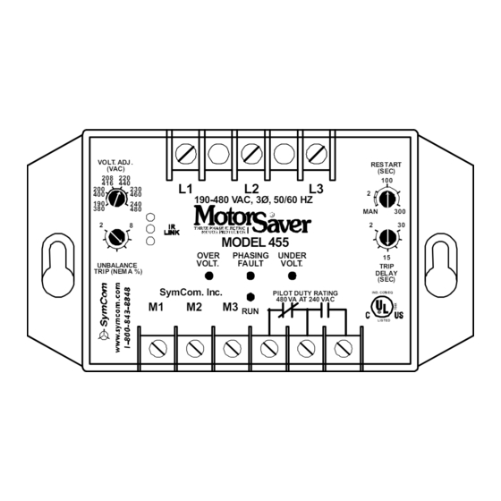
The Model 455, 3-phase, 190-480VAC voltage monitor combines line and load-side monitoring to
alert the user of contactor failure. Line-side monitoring will protect the motor from damaging power
conditions including high and low voltage, voltage unbalance, single-phasing, phase reversal and
rapid cycling. The Model 455 is now equipped with an infrared LED to communicate with the
hand-held diagnostic tool—Informer MS Edition—to display trip points, real-time data, and the
last 20 faults and 32 motor starts. Motor run hours, also displayed by the Informer MS, can
now be reset on the 455.
CONNECTIONS
1. Mount the MotorSaver
wet or dusty, it should be mounted in a NEMA 4 or 12 enclosure.
2. Connect L1, L2, and L3 on the MotorSaver
3. Connect M1, M2 and M3 to the power lines on the LOAD SIDE of the motor starter.
NOTE: If a 2-pole contactor is used, jump the hard-wired line from the L side terminal (the wire not
connected through the contactor) to its corresponding M terminal.
If load-side protection is not desired, connection to the M terminals is not required—the
Model 455 will operate as a line side only voltage monitor in this configuration.
4. Connect the output relay to the circuitry to be controlled. Connect the normally open contact in
series with the magnetic coil of the motor starter as shown in Figure 1.
A
B
C
L1
L2
L3
MS455
M1
M2
M3
CONTROL
POWER
24 - 240 VAC
Figure 1. 3-Pole Contactor Wiring Diagram
NOTE: L1 and M1 must be connected to the same supply line as shown. Similarily, L2 and M2, as
well as L3 and M3 must be connected to the same supply lines.
INSTALLATION INSTRUCTIONS FOR
®
in a convenient location in or near the motor control panel. If the location is
®
OL
OL
MOTOR
OL
THERMOSTAT
MAG.
OPTIONAL
OL
M
T
COIL
START
STOP
HAND
M
OFF
AUTO
PILOT
SYMCOM'S MOTORSAVER
MODEL 455
to the LINE SIDE of the motor starter.
A
B
C
L1
L2
MS455
M1
M2
M3
CONTROL
POWER
24 - 240 VAC
Figure 2. 2-Pole Contactor Wiring Diagram
2880 North Plaza Drive, Rapid City, South Dakota 57702
222 Disk Drive, Rapid City, SD 57701
(800) 843-8848 · (605) 348-5580 · fax (605) 348-5685
(800) 843-8848 www.symcom.com
®
OL
MAGNETIC
OL
CONTACTOR
OL
L3
THERMOS TAT
MAG.
OPTIONAL
OL
M
COIL
STOP
HAND
OFF
AUTO
PILOT
www.symcom.com
MOTOR
T
START
M
Advertisement
Table of Contents

Subscribe to Our Youtube Channel
Summary of Contents for Motor Saver SYMCOM'S MOTORSAVER 455
- Page 1 INSTALLATION INSTRUCTIONS FOR ® SYMCOM’S MOTORSAVER MODEL 455 BE SURE POWER IS DISCONNECTED PRIOR TO INSTALLATION! FOLLOW NATIONAL, STATE AND LOCAL CODES. READ THESE INSTRUCTIONS ENTIRELY BEFORE INSTALLATION. The Model 455, 3-phase, 190-480VAC voltage monitor combines line and load-side monitoring to alert the user of contactor failure.
- Page 2 SETTINGS 1. LINE VOLTAGE ADJUSTMENT: VOLT. ADJ . RES TART (VAC) (SEC) Rotate the VOLT. ADJ. (VAC) knob to 190-480 VAC, 3Ø, 50/60 HZ the nominal 3-phase line voltage feeding the motor to be protected. MODEL 455 OVER PHASING UNDER The Model 455 will automatically VOLT.
- Page 3 TROUBLESHOOTING SYMPTOM SOLUTION Check the RESTART DELAY knob. If it is set to the manual (MAN) The RUN light does not blink position, the Model 455 is in manual reset mode. Turn the on initial power-up and all RESTART DELAY to “2” for several seconds until the output three fault lights are on.
- Page 4 MODEL 455 SPECIFICATIONS 190–480VAC (nominal) 3-Phase Line Voltage 475–600VAC (Model 455-575) 50*/60Hz Frequency Low Voltage (% of setpoint) Trip Reset High Voltage (%of setpoint) Trip 110% Reset 107% Voltage Unbalance (NEMA) 2–8% Trip 4.5% Reset Trip Delay Time Low and High Voltage, 2–30 seconds (adjustable) and Voltage Unbalance 2 seconds (fixed)
Need help?
Do you have a question about the SYMCOM'S MOTORSAVER 455 and is the answer not in the manual?
Questions and answers