Advertisement
- 1 Use
- 2 Function rotary switches
- 3 Operation
- 4 Test function
- 5 Constant lighting control with FIH65B
- 6 Typical connection
- 7 Teaching in FDG71L-230V
- 8 Clear device configuration
- 9 Teaching-in sensors
- 10 Saving light scenes
- 11 Retrieving light scenes
- 12 Switch-on confirmation telegrams
- 13 Switch-off confirmation telegrams
- 14 Configure FDG71L
- 15 Cable fixation
- 16 DALI-System
- 17 Documents / Resources
Use
Only skilled electricians may install this electrical equipment otherwise there is the risk of fire or electric shock!
Temperature at mounting location:
-20°C up to +50°C.
Storage temperature: -25°C up to +70°C.
Relative humidity: annual average value <75%.
valid for devices from production week
18/18 (see bottom side of housing)
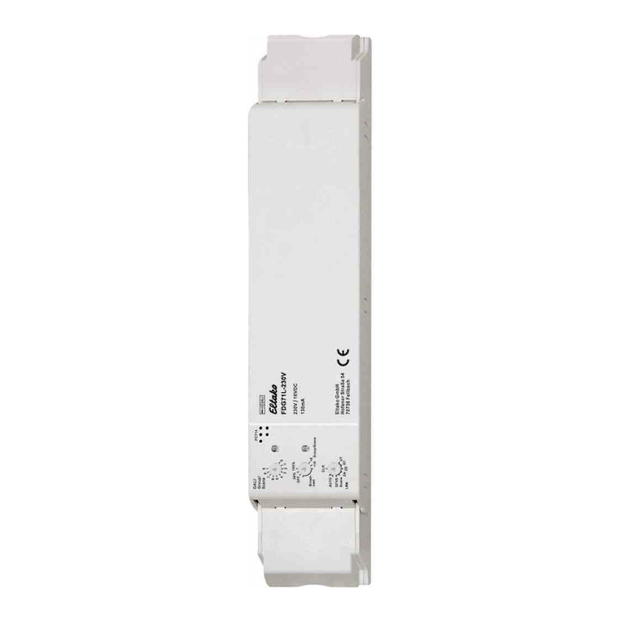
Wireless DALI gateway, bidirectional. 2 watt standby loss.
Installation for example in suspended ceilings and lamps. 252mm long, 46mm wide and 31mm high. With cable fixation.
Power supply 230V at terminals N and L.
16V DC/130mA can be connected to the DALI terminals +/- for up to 64 DALI devices.
The gateway FDG71L controls DALI devices with EnOcean wireless transmitters.
Groups 0-15 can be controlled and the broadcast command can be sent. In addition DALI scenes 0-15 can be recalled.
DALI installations, which are to be fully controlled with the FDG71L, must be configured in groups 0-15.
The configuration software or control modules for it are offered from well-known manufacturers of DALI components (eg Tridonic DALI XC).
The FGD71L internally saves the dimming value for each of the groups 0-15 and supplies this value as feedback. The same feedback telegrams are generated as for an FUD71.
The feedbacks of the device addresses correspond to the dimming values of the DALI groups 0-15 in ascending order.
Feedbacks can be converted by the
PCT14 for each individual group of dimming value telegrams (%) to pushbutton telegrams (ON/OFF). Feedbacks can then control actuators.
The FGD71L fulfils the functions of the DALI master and the DALI power supply.

Wireless pushbuttons always need to be double-clicked when they are taught-in manually in the FDG71L. CLR only needs a single click.
A direction pushbutton or universal pushbutton with identical ID and identical pushbutton cannot be taught in several times in different groups. The group last selected is always valid. Therefore, a pushbutton can either switch only one group or broadcast to all groups.
One FBH per group can also be taught in. With a manual teach-in this always acts dependent on brightness. With PCT14 you can also set the brightness threshold. The delay time for switch-off after no motion is detected can be set together in minutes (1.. 60) for the FBH devices of all groups. The default is 3 minutes.
Function rotary switches

Operation
After switching on the power supply, the complete DALI bus is scanned and the red LED on the FDG71L flickers for several seconds. All DALI devices present will be recognized with their short address and following adjustments will be read: MIN Level, Dimmspeed (fade rate & fade time) and group affiliation. The least possible minimum brightness is determined from this data and the dimming speed for groups 0...15. All DALI devices in a group must have the same dimming speed, so each group can be dimmed at an individual speed. The allowable range for the FADE RATE is 16 to 179 steps per second. The FADE TIME must be set to a value higher than 0.7s. The DALI scan must be performed each time a change of the settings has been made. For this, the lower rotary switch of the FDG71L must be set to AUTO again.
Test function
Turn the middle rotary switch to
100% stellen = all DALI operating devices switch on at 100%.
Turn to 20% = all DALI operating devices switch on at 20%.
Turn OFF = all DALI operating devices switch off.
Universal pushbutton:
Switch on and off or dim up and down, the direction change is made by a short release of the pushbutton.
Direction pushbutton:
'Switch on and dim up' on one side and 'Switch off and dim down' on the other side.
A double-click on the switch-on side activates automatic dim-up to full brightness at dim speed.
ZE: Switches on at maximum brightness (100%). A dimming value in % can be defined with PCT14.
ZA: Switches off. 'Soft OFF' can be deactivated with PCT14.
Rotary switch: press or turn to switch on. Dim up by turning to the right of turn to the left to dimm donw. Press to switch off. A broadcast is not possible.
FBH: A wireless motion detector and brightness sensor FBH can be taught-in.
It is only evaluated as a motion detector. A brightness threshold at which the lighting is switched on dependent on the brightness (in addition to motion) can be defined with PCT14. If no motion is detected, switch-off takes place after 3 minutes. The switch-off delay can be set between 1 and 60 minutes.
Via PCT14, it´s possible to set a time which the FBH is blocked for a selected time after a manual switching action via pushbutton. With a short press on the on side of a direction pushbutton, the FBH will be activated again.
Constant lighting control with FIH65B
The automatic brightness control switches on automatically once the FIH65B is taught in. The required brightness is set using a pushbutton and the first brightness value then received from the FIH65B becomes the target brightness. This is kept constant automatically by the FDG by incoming brightness values from the FIH65B. After every change in brightness (dimming) by the pushbutton, the brightness value then received from the FIH65H becomes the new target brightness. If the target brightness is set by the PCT14 or saved with a ‚direction pushbutton for target brightness', it then becomes permanent. A change in brightness by pushbutton is then overridden by the permanently set target brightness. If an FBH is also taught in, the light is switched on in case of motion detection and undershot target brightness and switched off in case of no motion detection or exceeded target brightness. Switching off by pushbutton deactivates automatic control by FBH or FIH. Central pushbutton, scene pushbutton and dimming values by PC also result in deactivation. Automatic control is reactivated by briefly pressing the pushbutton on the switchon side of the direction pushbutton.
Save target brightness: Press top of direction pushbutton for target brightness. The current brightness sent by FIH65B is saved.
Clear target brightness: Press bottom of direction pushbutton for target brightness.
FTK: When the window is opened, the light switches on at maximum brightness (100%). When the window is closed, the light switches off.
GFVS: With a dimming value telegram for one group, the blocking bit only acts on the group pushbutton for this group. With Broadcast, you can still change the group. With a dimming value telegram for all groups (Broadcast), the blocking bit only acts on the Broadcast pushbutton. You can still change the groups using group pushbuttons.
The red LED lights up when a wireless signal is received.
The green LED lights up when a confirmation signal is received.
Typical connection

Teaching-in wireless sensors in wireless actuators
All sensors must be taught-in in the actuators so that they can detect and execute commands.
Teaching in FDG71L-230V
The teach-in memory is clear on delivery from the factory. To ensure that a device was not previously taught-in, clear the complete memory:
Turn the lower rotary switch to CLR.
The red LED flashes at a high rate. Within 10 seconds, turn the upper rotary switch three times to right stop (turn clockwise) and back again. The LED stops flashing and goes out after 2 seconds. All taught-in sensors are cleared.
Clear single taught-in sensors in the same way as in the teach-in procedure, except that you set the lower rotary switch to CLR. The LED p reviously flashing at a high rate goes out.
Clear device configuration
Set the lower rotary switch to CLR. The red LED flashes at a high rate. Within the next 10 seconds, turn the upper rotary switch six times to left stop (turn anticlockwise) and away again. The LED stops flashing and goes out after 5 seconds. The factory settings are restored.
Teaching-in sensors
- Turn the middle rotary switch to +0 = group 0 to 9 or turn to +10 = group 10 to 16 or turn to Broadcast = Broadcast
- Turn the upper rotary switch to the required group 0 to 9, e.g. middle +0 and upper 9 = group 9 or middle +10 and upper 6 = group 16
- Set the lower rotary switch to the required teach-in function. The red LED flickers at a low rate.
UT = Teach in universal pushbutton
RT = Teach in direction pushbutton, direction pushbuttons are automatically taught-in fully when pressed. Depending on where the button is pressed, the functions for switch-on and dim-up are defined on one side and switch-off and dim-down on the other side.
ZE = teach in 'central on'
ZA = teach in 'central off'
Scene = pushbutton for DALI scene re call (with the upper and middle rotary switch, the required DALI Scene 0..15 is selected); teach in FBH, FIH and FTK.
GFVS = Teach-in GFVS and rotary switch, during teaching-in, confirmation telegrams are activated and a confirmation telegram is automatically sent. - Quickly confirm the pushbutton to be taught-in by pressing it 2x in a row ('double-click'). The LED goes out.
A pushbutton (rocker end) can not be taught in several groups.
To teach-in further sensors, turn the lower rotary switch briefly away from its position. Continue the procedure from pos 1. After teach-in, set the lower rotary switch to AUTO and the middle rotary switch to Broadcast.
Saving light scenes
Up to four brightness values can be saved using a 4-way light scene pushbutton.
- Set the required brightness value using a previously taught-in pushbutton or the GFVS.
- Within 60 seconds, press one of the four rocker ends of the previously taught-in light scene pushbutton for longer than 3 seconds but less than 5 seconds to save the brightness value.
- To save other light scenes, repeat from point 1.
Retrieving light scenes
Up to four brightness values are retrievable using a 4-way light scene pushbutton:
pushbutton with double rocker;
top left = light scene 1 (ex factory 30%),
top right = light scene 2 (60%),
bottom left = light scene 3 (100%) and bottom right = light scene 4 (0%).
With PCT14, the brightness value of the 4 light scenes for groups 0-15 can be changed. If MASK is chosen for a scene, than this group stays unchanged at scene´s call.
Switch-on confirmation telegrams
On delivery ex works the confirmation telegrams are switched off. Set the lower rotary switch to CLR. The red LED flashes nervously. Now within 10 seconds turn the upper rotary switch 3 times to the left (anticlockwise) and then back away. The red LED stops flickering and goes out after 2 seconds. The confirmation telegrams are switched-on.
Switch-off confirmation telegrams
Set the lower rotary switch to CLR. The red LED flashes nervously. Now within 10 seconds turn the upper rotary switch 3 times to the left (anticlockwise) and then back away. The red LED goes out immediately. The confirmation telegrams are switched-off.
Configure FDG71L
- Turn off the power supply of the FDG71L
- Plug-in the DAT71
- After about 10s., the red LED of the FDG71L goes off
- PCT14: 'connect'
- Configure the FPLG71L with PCT14; F ollowing can be changed:
- Parameters for FBH
- Parameters for FIH65B
- Light scenes in %
- Dimming value in % for one (RECAL MAX LEVEL)
- PCT14: 'disconnect'
- Unplug the DAT71
- Turn on the power supply of the FDG71L

When an actuator is ready for teach-in (the LED flashes at a low rate), the very next incoming signal is taught-in. Therefore, make absolutely sure that you do not activate any other sensors during the teach-in phase.
Cable fixation

The cable must be fastened with standard cable ties (width <3.6mm).
DALI-System
In the system the DALI Gateway acts as a central control component (master controller), which also ensures the power supply of the DALI interface. The DALI devices, eg. DALI ballasts, operate as command receiver (slave), which only return states or status messages to the master upon request. It is solely the task of the DALI Gateway to send commands received via wireless control to the DALI line and to control the devices. The use of other DALI control components in multi-master mode, eg an additional DALI center, a DALI potentiometer or mains voltage pushbuttons, are unnecessary and may lead to malfunctions in the DALI system in some cases. For this reason it is necessary to remove other components of the system - especially when retrofitting existing DALI installations.
EnOcean wireless
| Frequency | 868.3 MHz |
| Transmit power | max. 10 mW |
Hereby, Eltako GmbH declares that the radio equipment type FDG71L-230V is in compliance with Directive 2014/53/EU.
The full text of the EU declaration of conformity is available at the following internet address: eltako.com
Must be kept for later use!
Eltako GmbH
D-70736 Fellbach
Technical Support English:
Michael Thünte +49 176 13582514 thuente@eltako.de
Marc Peter +49 173 3180368 marc.peter@eltako.de
eltako.com

Documents / Resources
References
Download manual
Here you can download full pdf version of manual, it may contain additional safety instructions, warranty information, FCC rules, etc.
Advertisement


Need help?
Do you have a question about the FDG71L-230V and is the answer not in the manual?
Questions and answers