Download Print this page
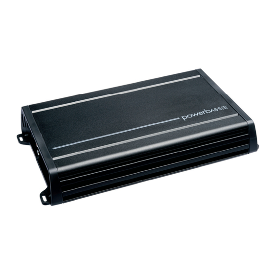
PowerBass ACS-2120 Owner's Manual

PowerBass ACS-2120 Owner's Manual

Acs compact class a/b amplifier

Advertisement

Quick Links

ACS-2120
ACS-4120
ACS-4090
ACS COMPACT CLASS A/B AMPLIFIER
Owners Manual
Please read through this manual to familiarize yourself with your new amplifi er. Should your PowerBass
AutoSound mobile amplifi er ever require service, you will need to have the original dated receipt.

Advertisement

loading
Need help?

Need help?

Do you have a question about the ACS-2120 and is the answer not in the manual?

Questions and answers

Subscribe to Our Youtube Channel

Summary of Contents for PowerBass ACS-2120

  • Page 1 ACS-4090 ACS COMPACT CLASS A/B AMPLIFIER Owners Manual Please read through this manual to familiarize yourself with your new amplifi er. Should your PowerBass AutoSound mobile amplifi er ever require service, you will need to have the original dated receipt.
  • Page 2 In the interest of safety, PowerBass USA highly recommends listening at lower volume...
  • Page 3 Variable Gain Control INSTALLATION EXPERIENCE Installation of PowerBass mobile amplifiers requires detailed knowledge of electronics wiring and proper speaker impedance. We strongly recommend installation by an authorized PowerBass dealer. This Owners Manual only provides general installation and operation instructions. If you have any reservations about your installation skills, please contact your local PowerBass dealer for assistance.
  • Page 4 MOUNTING THE AMPLIFIER Fig.1 Mounting Amplifier To keep your PowerBass amplifier running at top performance, choosing the proper location is of utmost importance. For this reason the amplifier should be mounted in a location which will allow air to circulate freely.
  • Page 5 The floor of the trunk, under a seat, or on the back of the rear seat. For alternate installation locations, please consult your authorized PowerBass Dealer. NOTE: Do not use a drill with driver bit to mount the amplifier. Excessive force could cause the plastic mounting feet to crack.
  • Page 6 CONTROL PANEL LAYOUT ACS-2120 CONTROL PANEL LAYOUT ACS-4090 / ACS-4120 Fig.2 Panel Layout...
  • Page 7 11. REM (Remote Input Connection) All PowerBass AutoSound amplifiers can be turned on by applying 12 volts to this terminal. This can be found on the rear of the source unit in the form of an electric antenna output, or a remote output. If this is not available you can wire to the ACC position on the key.
  • Page 8 POWER WIRING and SIGNAL CONNECTIONS LPF/HPF LO W INPU T ACS-21 20 CAR RADIO DC 14.4V Fig.4 Low Level Input using RCA – BATTERY RCA INTERCONNECT WIRING Choose the correct length and style of RCA interconnects for your needs. Always use high quality RCA audio cables (not supplied) for signal connections—those with multiple layers of shielding or a twisted pair variety provides better noise rejection.
  • Page 9 These amplifiers are designed to work within a 9 to 16 volt DC range. Before any wires are connected, the vehicles electrical system should be checked for correct voltage supply with the help of a voltmeter. First, check the voltage at the battery with the ignition in the OFF position. The voltmeter should read no less than 12V.
  • Page 10 REM on the amplifier using a Philips (cross) type screwdriver. FUSE REQUIREMENTS While the panel on your PowerBass amplifier incorporates one or more fuses, these do nothing to protect the vehicle from a dangerous short circuit. It is absolutely vital that the main power lead to the amplifier(s) in the system be fused within 18-inches (45cm) of the connection to the vehicle battery.
  • Page 11 HIGH LEVEL CONNECTIONS (Optional) High Level inputs have been included to connect the amplifier to a radio without low-level outputs (i.e. factory radio). This plug-in terminal will allow you to connect directly to the speaker output of the radio without the need of an external adapter.
  • Page 12 SET UP ADJUSTMENTS GAIN Fig.5 GAIN Control Input Sensitivity Control Input Gain Adjustment This control allows you to match the input level of the amplifier to the output level of your head unit. Matching the input can be accomplished in three simple steps: Set the volume of GAIN on the amplifier to Min (completely counter clock wise).
  • Page 13 Maintaining proper impedance is critical when wiring the Class AB model amplifiers. Improper wiring can cause severe damage to BOTH the woofer and the amplifier. Detailed wiring diagrams are supplied with all PowerBass woofers. IF YOU ARE NOT EXPERIENCED OR UNCOMFORTABLE READING THE WIRING DIAGRAMS CONSULT...
  • Page 14 Speaker Output Connections 2 Channel Model ( ACS-2210) 2-Channel Speaker Output Connection FULL RANGE SPEAKERS 2 Ohms 2 Ohms Minimum Minimum Fig.11 2-CH Speaker Connection (Do not connect total impedance under 2 ohms) 1-Channel (Bridged Mode) Speaker Output Connection SUBWOOFER 4 Ohms Minimum SWITCH POSITION X–OVER...
  • Page 15 Speaker Output Connections 4 Channel Model ( ACS-4120) / (ACS-4090) 4-Channel Speaker Output Connection FRONT REAR FULL RANGE SPEAKERS 2 Ohms 2 Ohms Minimum Minimum 4 Channel • REAR ACS-41 20 FRONT 2 Ohms 2 Ohms Minimum Minimum FULL RANGE SPEAKERS Fig.13 4-CH Speaker Connection (Do not connect total impedance under 2 ohms)
  • Page 16 CAUTION! When bridging the speaker outputs, the amplifier must see a 4 ohm load or higher. Below 4-ohms will cause internal damage to the amplifier. FRONT 3-Channel Stereo/Mono Speaker Output Connection 4 Ohm SUBWOOFER (4-OHM minimum) REAR 4 Channel • REAR ACS-41 20 FRONT...
  • Page 17 Miscellaneous: ______________________________________________________ This manual is the exclusive property of PowerBass USA, Inc. Any reproduction of this manual, or use other than its intentions is strictly prohibited without the express consent of PowerBass USA, Inc. © Copyright 2017 PowerBass USA, Inc.
  • Page 18 NOTE: If the Status L.E.D. is activated and glows RED with no speakers connected to the amplifier, and all the power connections are correct, this would indicate an internal problem with the ampli- fier. Contact PowerBass USA or your local dealer.
  • Page 19 SPECIFICATIONS FOR AUTOSOUND COMPACT A/B AMPLIFIERS ACS-2120 ACS-4090 ACS-4120 Two Channel Models 4 Ohms RMS Power (Watts) 60 x 2 45 x 4 60 x 4 2 Ohms RMS Power (Watts) 120 x 2 90 x 4 120 x 4...
  • Page 20 NOTES:...
  • Page 21 NOTES:...
  • Page 22 Some states do not allow limitations on the length of an implied warranty, so this limitation may not apply. No person is authorized to assume for PowerBass any other liability in connection with the sale of this product.
  • Page 24 PowerBass Autosound – A division of PowerBass USA, Inc. 2133 S. Green Privado – Ontario, CA 91761 Tel. (909) 923-3868 – Fax (909) 923-8048 www.powerbassusa.com...

This manual is also suitable for:

Acs-4120Acs-4090