Advertisement
Quick Links
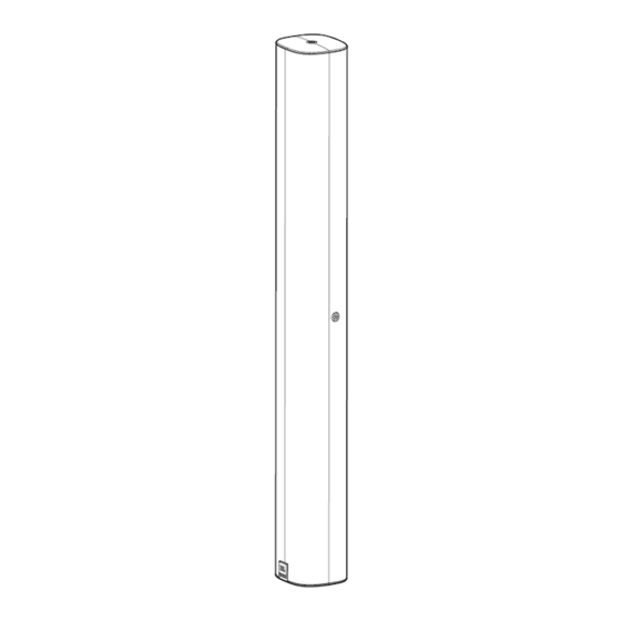
COL Column Speaker Installation Guide
COL 800
COL 600
JBL-COL800-BK and
JBL-COL600-BK and
)
JBL-COL800-WH
JBL-COL600-WH
Included Hardware
(not to scale)
)
3 pieces M6 x 12 mm bolts with flat washers & lock washers
3 pieces M6 x 20 mm bolts with flat washers & lock washers
3 pieces M6 x 28 mm bolts with flat washers & lock washers
(Note: Flat washers & lock washers are captive on the bolts.
One additional of each bolt is provided for backup.)
4 mm hex key
2-part Low-Profile Swivel (Pan) / Tilt
WALL BRACKET ASSEMBLY
Consists of:
• SPEAKER-SIDE of Bracket
• WALL-SIDE of Bracket
Decorative Trim piece for WALL-SIDE BRACKET (not shown)
•
2 pieces L-BRACKETS
TRIM COVER (for WALL BRACKET ASSEMBLY)
Ver 1.0
Advertisement

Related Manuals for JBL COL Series


Summary of Contents for JBL COL Series
- Page 1 Consists of: • SPEAKER-SIDE of Bracket • WALL-SIDE of Bracket Decorative Trim piece for WALL-SIDE BRACKET (not shown) • 2 pieces L-BRACKETS TRIM COVER (for WALL BRACKET ASSEMBLY) COL 800 COL 600 JBL-COL800-BK and JBL-COL600-BK and JBL-COL800-WH JBL-COL600-WH Ver 1.0...
- Page 2 Important Safety Instructions 1. Please read and keep all safety and user instructions. 2. This product is intended for installation by professional installers only! This document is intended to provide professional installers with basic installation and safety guidelines for this product in typical fixed-installation systems. Please read this document and all safety warnings before attempting installation.
- Page 3 WATCH FOR THIS SYMBOL: The exclamation point, within an equilateral triangle, is intended to alert the user to the presence of important operating and maintenance (servicing) instructions in the literature accompanying the product. WARNING: No naked flame sources – such as lighted candles – should be placed on the product. CAUTION: To be installed by instructed, or skilled, persons only.
- Page 4 Note that the BRACKET ASSEMBLY consists of a SPEAKER-SIDE and a WALL-SIDE. 1.0) Mounting WALL-SIDE BRACKET: 1.1) Run the wiring from the power amplifier to the location desired for mounting the JBL COL loudspeaker. 1.2) Secure WALL-SIDE BRACKET to wall using the appropriate installer-selected attachment hardware, and using a level to ensure that the WALL-SIDE BRACKET is straight.
- Page 5 2.0) Mounting SPEAKER-SIDE BRACKET to COL speaker: 2.1) Identify the COL speaker’s two back panel mounting points, labeled on the back panel as “WALL BRACKET POINTS”. Remove the silicone caps from those points, exposing the threaded inserts. 2.2) Attach the 2-part SPEAKER-SIDE BRACKET to COL speaker using two M6 x 20 mm bolts (with flat washers and lock washers).
- Page 6 3.0) Connecting SPEAKER-SIDE BRACKET to WALL-SIDE BRACKET to form SWIVEL/TILT BRACKET ASSEMBLY: 3.1) After sliding TRIM COVER onto WALL-SIDE BRACKET, loosely thread one of the M6 x 12 mm bolts (with flat washer and lock washer) into the bottom PIVOT hole of the SPEAKER-SIDE BRACKET. This bolt becomes the PIVOT BOLT. 3.2) Slide COL speaker (with SPEAKER-SIDE BRACKET attached) onto the WALL-SIDE BRACKET, sliding the PIVOT BOLT into the HOOK SLOT of the WALL-SIDE BRACKET.
- Page 7 SWIVEL (PAN) / TILT WALL BRACKET ASSEMBLY Dimensions and Settings Dims in mm [in]...
- Page 8 OPTION B: WALL SURFACE MOUNTING VIA INCLUDED L-BRACKETS Note that the L-BRACKETS can be attached to either the top and bottom of the speaker (via threaded inserts located on the top and bottom panels) or to the sides of the speaker (via threaded inserts located in the left and right panels of the speaker). The following instructions and drawings are for using the side points.
- Page 9 4.0) Install L-BRACKETS to the Wall and Side Insert Points: 4.1) Run the wiring from the power amplifier to the location desired for mounting the JBL COL loudspeaker. 4.2) Secure L-BRACKET to wall using the appropriate installer-selected attachment hardware, and using a level to ensure that the L-BRACKETS are plumb.
- Page 10 4.3) Remove the silicone caps from over the left-side and right-side threaded insert points, exposing the metal threaded inserts. Note: There are two holes in the column-end part of each L-BRACKET – one for situating the column closest to the wall and one for spacing farther out from the wall.
- Page 11 5.0) Installing L-BRACKETS to the Wall and TOP/Bottom Insert Points: 5.1) Apply same process from 4.1 and 4.2 for running wiring and attaching L-brackets to wall. For use with top and bottom insert points, space brackets so that inner-most screws holes of the L-BRACKETS (wall side) are the following distances apart: Distance Between Innermost Screws COL600 521 mm (20.5 in)
- Page 12 5.2) Remove the silicone caps from over the top and bottom threaded insert points and remove the bolts that are holding the end caps, exposing the inserts (these removed bolts will not be re-used). Note: There are two holes in the column-end part of each L-BRACKET. For the top and bottom points on the speaker, the outer-most BRACKET hole must be used.
- Page 13 COMPLETING THE INSTALLATION 6.0) SECONDARY SAFETY CABLE Attach a properly load-rated safety cable (not included) to the back-panel M6 threaded insert point on the back panel marked “Safety Cable,” using hardware that does not incur interference with the wall. Attach the other end of the safety cable to a secure independent attachment point on the building structure.
- Page 14 7.3 TERMINAL COVER – Remove the TERMINAL COVER, plug in-line terminal connector into chassis socket. Run wire(s) downward and re-attach terminal cover using 3 included screws, making sure pressure insert (for resistance against water ingress) presses down on wires. The TERMINAL COVER may be left off if no resistance against water is needed. TERMINAL COVER (with 3 included screws).
- Page 15 8.1 GUIDE: Back Panel Drawings Top Threaded Insert for M6 Threaded L-Bracket Insert for Safety Cable M6 Threaded Insert for Safety Cable Tap Selector Rotary Switch M6 Threaded Inserts for Wall M6 Threaded Bracket Inserts for Wall Bracket Side Threaded Insert for L-Bracket Wiring...
- Page 16 8.2 GUIDE: Dimensions COL 800...
- Page 17 COL 600...
- Page 18 Physical Aim of Speaker COL 600 COL 800 110° total vertical coverage 60° total vertical coverage angle with aiming axis at -10° angle with aiming axis at -10° JBL Professional ǀ 8500 Balboa Blvd. ǀ Northridge, CA 91329 COL Install Guide 05/2023...
Need help?
Do you have a question about the COL Series and is the answer not in the manual?
Questions and answers