Advertisement
Quick Links
Advertisement

Summary of Contents for Talbotts T Series
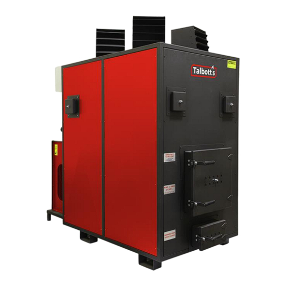
- Page 1 T-Range Manual Feed Space Heaters Ref: T- Range (HF) Operating Manual Issue 1, 23/08/19...
- Page 2 Purpose of the Manual This manual will assist the reader in the operation of the appliance safely and efficiently. It should be kept within close proximity of the appliance for easy access. All staff must have read and understood this manual in its entirety before operating or undertaking maintenance.
- Page 3 Technical Data Appliance Specification Unit Specifications T150 T300 T500 Length 1230mm 1450mm 1970mm 2295mm Width 914mm 914mm 1170mm 1170mm Height 1000mm 1700mm 1830mm 1995mm Weight 535kg 950kg 1388kg 1880kg Heat Output 25kW/Hr 50kW/Hr 100kW/Hr 150kW/Hr 180mm (7”) 180mm (7”) 200mm (8”) 255mm (10”) Flue Diameter Air Volume...
- Page 4 Ensure the appliance is technically sound at all times. The below must be adhered to: • maintenance intervals described in this manual are complied with • all necessary safety and protective devices are operational and checked before start up All staff operating this appliance must receive training by the manufacture or manufacture approved operatives.
- Page 5 Order Form for Replacement parts Please send completed form (by email preferably) to: Talbott’s Biomass Energy Systems Ltd Tel: 01785 813 772 Unit 13, Walton Industrial Estate Beacon Road Stone Email: stores@Talbott’s.co.uk Staffordshire ST15 0NN Company Name Contact Person Address Telephone No.
- Page 6 Limitations of Liability Talbott’s Biomass Energy Systems Ltd cannot accept liability for damage caused by Failure to follow manual instructions Failure to operate appliance within its design parameters A direct result of misuse or neglect in the manufacturers opinion Accidental damage to components Unauthorised retrofitting without manufacturers written approval Use of non-original replacement parts Failure of any component as a result of consequential damage by either...
- Page 7 Warranty Components All items are covered by the Talbott’s twelve month guarantee with the exception of the following: Please Note - Items marked (*) are covered by a 6 month warranty. Door Components Sight Glasses Door Rope Fan Unit Main Fan Belts Main Fan Pulleys Brickwork &...
- Page 8 BEFORE OPERATING THIS MACHINE ENSURE THAT: All guards and fences are securely fitted and correctly set in accordance with the current regulation. Appliance is cleaned out and has been checked over to instructions Loose clothing is either removed or fastened and jewellery removed That the correct fuel is being used The working area is well lit, clean and unobstructed Suitable PPE is available...
- Page 9 There are a number of points that must be adhered to • No accelerants should be used within the firebox for lighting or during operation (e.g. Thinners) • These appliances are designed to burn wood off-cuts and no plastics or other foreign matter should be burned within the firebox (this will cause smoke and residue within the appliance) •...
- Page 10 Combustion Fan Top Tube Top Tube The top tube is located across the top of the fire box and is attached to the combustion fan. Its purpose is to allow the air to pass through the holes running along the tubes length and evenly distribute it around the fire box.
- Page 11 Thermostat Thermostat with cover removed Main Fan Main Fan Description The main fan is situated at the rear of the appliance and is activated by the thermostat. Operation The fan has two main functions, firstly to distribute the hot air and secondly to cool the heat exchange to avoid overheating.
- Page 12 Cleaning The average usage of a Hand fed T-Range appliance is estimated at 8 hrs a day over a 5 day period. For every 40-60hrs run the machine should be turned off and cleaned. This is normally done on a weekly basis. To Clean Out the Heater Ensure Appliance has cooled down and switch off power.
- Page 13 Summer Heat Dump & Additional Ducting Description Ducted boxes replace the vented heads that a standard appliance is supplied with. These allow heat to be distributed to other locations or in the case of a summer heat dump vented to outside for use during the warmer periods. Operation There are numerous different sizes of ducted box available each one is built to order to suit the individual requirements of the customer but all follow the same principle.
- Page 14 Installation Guidelines Positioning Position of the heater is as important as any other part of the installation. Consideration must be given to the following points: • The heater must stand on a completely level non-combustible base capable of supporting its full weight. •...
- Page 15 The flue must satisfy all building, fire and heating regulations and be capable of with standing temperatures up to 980 Deg C. A straight vertical flue is in all cases the most efficient, if however bends have to be fitted never use more than two elbows, the angle of which must not be greater than 45 degrees.
- Page 16 The Clean Air Act 1993 and Smoke Control Areas Under the Clean Air Act local authorities may declare the whole or part of the district of the authority to be a smoke control area. It is an offence to emit smoke from a chimney of a building, from a furnace or from any fixed boiler if located in a designated smoke control area.
- Page 17 Fault Finding FAULT CAUSE REMEDY Appliance smoking Overloading - Reduce the amount being loaded into the firebox - Foreign material is being burned in combustion chamber Incomplete combustion - Clean appliance out - Check damper on chimney - Check operation of combustion air fan - Check top tube Appliance...
- Page 18 Hazard Analysis The following listed hazards; hazardous situations and hazardous events are taken from BSEN1050 ACTION BY HAZARD Design / Safeguarding / Information Mechanical hazards due to: Machine parts or work pieces, e.g.: a) shape; b) relative location c) mass and stability d) mass and velocity e) inadequacy of mechanical strength...
- Page 19 ACTION BY HAZARD Design / Safeguarding / Information Electrical hazards due to: Contact of persons with live parts (direct contact) Isolated within control panel Contact of persons with parts which have become live under faulty conditions (indirect contact) Interlock on panel door cuts power when actuated Approach to live parts under high voltage...
- Page 20 ACTION BY HAZARD Design / Safeguarding / Information Use of hand held machines resulting in a variety of neurological and vascular disorders Whole body vibration, particularly when combined with poor postures Hazards generated by radiation Low frequency, radio frequency radiation, micro waves Infrared, visible and ultraviolet light X and gamma rays Alpha, beta rays, electron or ion...
- Page 21 ACTION BY HAZARD Design / Safeguarding / Information 8.7 Inadequate design, location or identification of manual controls 8.8 Inadequate design, location of visual display units Combination of hazards Unexpected start-up, unexpected overrun / over-speed (or any similar malfunction) from: Failure / disorder of the control system 10.1 Restoration of energy supply after an 10.2...
- Page 22 19 Slip, trip and fall of persons (related to the machinery) Please refer to our Terms and Conditions of Sale. A copy is available on request or can be downloaded at https://www.talbotts.co.uk/terms-conditions/ Notes: 1. …………………………………………………………….. …………………………………………………………….. 2. …………………………………………………………….. ……………………………………………………………..