
Summary of Contents for Kromschroeder Lago Basic 0101/1001
- Page 1 Lago Basic 0101/1001 Boiler module/Mixer Operating and controller Installation Instructions Please observe the safety instructions and read through this manual carefully before commissioning the equipment.
-
Page 2: General Information
Safety information General information General information Warranty conditions Safety information If the system is not installed, commissioned, serviced and re- Power connection regulations paired professionally, this will render the manufacturer's war- Please note the connection conditions specified by your local ranty null and void. -
Page 3: Installation
Description General information To comply with applicable regulations, the General Function instructions for assembly and operation must be Control of a fixed flow temperature or a fixed return readily available at all times and must be handed flow temperature via control of a heat generator or a over to the responsible engineer when working on mixer. -
Page 4: Table Of Contents
Description General information General information Functions Operation without operating module Safety information Power connection regulations Control of the flow temperature Safety Mode of operation cooling Warranty conditions (only as 1001 mixer operation) ... - Page 5 Description General information Installation Remote controls The operating module Merlin BM, BM 8, Assembly / Dismantling Lago FB Dimensions Remote control FBR2 Electrical connection Controller Sensor resistances FBR Electrical connection, base Options ...
-
Page 6: Operation
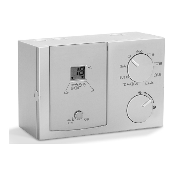
Explanation of the operating elements Operation Operation Key STL-test / Enter / Reset Explanation of the operating elements STL-test (RT without effect) => By pressing > 1 sec Rotating switch =>Burner on, for as long as key is pressed, display:HS- Automatic mode Temp flashes (no function as mixer) To the left:... -
Page 7: Display (Normal Mode "Run")
Display (normal mode "Run") Operation Display (normal mode "Run") The display shows the flow temperature of the heat gener- ator or the heating circuit. When the incremental encoder is rotated, the following temperatures are displayed: 1. Switch Outside temperature (S, arrow 1), 9-stage 2. -
Page 8: Starting Up
Modifying set values Starting up Starting up List of the User Set Values Starting up Designation Area Factory Values After the device has been properly installed (please ob- Run => Normal mode serve the switch position on the rear side of your device), Display level with shaft encoder switch on the power supply. -
Page 9: Explanatory Information
Set values Explanatory information The flow set temperature is increased by the set value Explanatory information Set values when the temperature drops below the required room tem- Room set temperature perature by 1 K. => High values lead to fast control and large heat genera- Only effective if an outside sensor or a room sensor tor temperature fluctuations. - Page 10 Set values Explanatory information Hot water set temp. (only in the case of boiler module) Flow temperature [°C] Setting the desired hot water temperature. This tempera- ture is stabilised in the storage tank for 24 h HW thermostat instead of HW sensor: Hot water prepara- tion in the event of short circuit on the sensor input.
-
Page 11: Settings Via Dip Switch (Rear Side)
Set values Explanatory information Settings via DIP switch (rear side) switched off before the minimum boiler temperature has been reached + 5 K. Switch 1 - 5 only valid in the case of HS controller without Parallel pump operation (F + operating module OFF =>... -
Page 12: Functions
Functions Explanatory information If an outdoor sensor is connected, a weather-dependent Functions calculation of the flow set value is performed. Operation without operating module If a room sensor is connected, a room temperature de- When the controller is operated without an operating mod- pendent regulation to the specified room set value is acti- ule (correspondingly, in the event of the bus connection to vated. -
Page 13: Mode Of Operation Cooling (Only As 1001 Mixer Operation)
Functions Explanatory information Mode of operation cooling (only as 1001 mixer opera- Warm-up temperature (HS min. – 5 K) tion) Reduces operation in condensation zone. The circulation The air conditioning by the central automatic controller is pumps are switched off and the mixers are shut until the supported. -
Page 14: Dhw Relief
Special functions Explanatory information Should the outdoor sensor be defective, the frost protec- Special functions tion temperature is included in the flow calculation. EEPROM check DHW Relief Every 10 minutes, a check is conducted automatically in The charging pump is not switched until the boiler temper- order to establish whether the settings of the controller lie ature exceeds the storage tank temperature by 5 K. -
Page 15: Assembly / Dismantling
Assembly / Dismantling Installation Installation Mounting material, e.g.: Assembly / Dismantling Version 1 => Through the hole at the side Mounting holes Mounting holes, for assembly on switch box Breakthrough for leading cable through Version 2 => From the front Dimensions... -
Page 16: Electrical Connection Controller
Electrical connection Controller Installation Electrical connection Controller ~230 V; Relay switching capacity 2(2) A, ~250 V Safety extra-low voltage 1 N-conductor, mains 11 - 14 CAN BUS 2 Power supply, unit 15 - 17 FBR2 alternatively: 3 Power supply, relay 15 + 16 Lago switch (bridge 2 to 3) or room thermostat... -
Page 17: Electrical Connection, Base
Electrical connection, base Installation Electrical connection, base Safety extra-low voltage ~230 V; Relay switching capacity 2(2) A, ~250 V 11 - 14 CAN BUS 1 N-conductor, mains 15 - 17 FBR2 2 Power supply, unit alternatively: 3 Power supply, relay 15 + 16 Lago switch (bridge 2 to 3) or room thermostat... -
Page 18: Options
Options Installation BUS terminating resistor Options Provided no separate regulations for protecting the relay apply, a bridge to supply the relay must be connected be- tween terminals 2 and 3. Attention: In case of installation in systems with Stand-alone Mixer control with room device (Lago FB, BM8, etc.) -
Page 19: System Diagrams
System diagrams Installation System diagrams BUS ID: „--„ => Boiler sensor required °C : Setting of the flow temperature Boiler controller with direct heating circuit and Hot Note settings on the rear side of the controller water Heating circuit operation when: ... -
Page 20: Boiler Controller With Header Pump / Mixer Motor Expansion
System diagrams Installation Boiler controller with Header pump / mixer motor ex- pansion... - Page 21 System diagrams Installation °C F / v Set mixer dynamics 0101 Boiler controller with collector pump In the case of weather guidance => Outside temperature BUS ID: „00„ => Boiler sensor required required Note settings on rear side of controller. °CD Set room set temperature and No heating circuit!
-
Page 22: Boiler Controller In Cascade Operation
System diagrams Installation Boiler controller in cascade operation... -
Page 23: Remote Controls
Remote controls Installation Remote controls Remote control FBR2 The operating module Merlin BM, BM 8, Lago FB The controller permits connection of an operating module via a bus line. The operation-control module allows various operation-control functions and monitoring functions for the system values to be relocated to the main controlled zone –... -
Page 24: Sensor Resistances Fbr
Remote controls Installation Installation location: All system-specific parameters can be set and interrogated In reference / main living room of the heating circuit using the omfort oft parameterisation software. The pa- (on an inside wall of the room). rameters can be saved, displayed graphically and evaluat- ... -
Page 25: Sensors
Sensors Installation Sensors Strap-on sensor VF (VFAS) v Outside sensor AF (AFS) S Order no. VF, 5 kΩ, 3 m, ø 6.0x50: 99 679 073 Order no. AF, 5 kΩ: 99 679 030 Order no. VFAS, 1 kΩ, 3 m, ø 6.0x50: 99 679 051 Order no. -
Page 26: Sensor Values / Characteristic Curve
Errors Installation Sensor values / characteristic curve Errors Temperature 5 kOhm NTC 1 kOhm PTC -60 °C 698961 When there is an error, the corresponding error number -50 °C 333908 flashes. -40 °C 167835 ... -
Page 27: Technical Data
Technical data Glossary Technical data Flow and return flow temperature Supply voltage complying with AC 230 V 10 % The flow temperature is the temperature to which the heat EN 60038 source heats the water that transfers the heat to the con- Power consumption Max. - Page 28 65 °C every 20th heating period Elster GmbH or at least once a week as protection against these bacte- Geschäftssegment ria. Comfort Controls Kuhlmannstraße 10 31785 Hameln www.kromschroeder.de Malfunctions due to improper operation or settings are not covered by the warranty.
Need help?
Do you have a question about the Lago Basic 0101/1001 and is the answer not in the manual?
Questions and answers