
Subscribe to Our Youtube Channel
Related Manuals for Assured Automation 38 Series

Summary of Contents for Assured Automation 38 Series
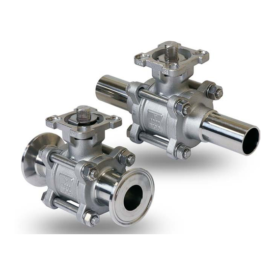
- Page 1 1-800-899-0553 assuredautomation.com 38 Series Stainless Steel 2-way Ball Valves Installation, Operation, & Maintenance Manual Scan for more product information Doc. AA-38-IOM-2023.05.15...
-
Page 2: Table Of Contents
TABLE OF CONTENTS 1. General Precaution 1.1. Material Section ..................1 1.2. Pressure-Temperature Rating ..............1 1.3. Fluid Thermal Expansion ................1 1.4. Static Electric Effect..................1 1.5. Liquids with High Fluid Velocity .............1 1.6. Throttling Service..................1 1.7. Disassembling Valve.................1 1.8. Skin Contact with the Valve Surface ............1 1.9. -
Page 3: General Precaution
1. General Precaution 1.1. Material Section Material deterioration is determined by the contained fluid. The need for period inspection must be determined by user based on the contained fluid. Among possible cases of deterioration are carbide phase conversion to graphite, oxidation of ferrite materials, decrease in ductility of carbon steels at low temperature (even in applications above - 29°C). -
Page 4: Product Specification
c. Options of threaded end, socket weld end, or butt weld end with face to face dimensions according to DIN3202-M3 d. Three-Piece design enables in-line maintenance e. Special pyramidal stem design for exceptional stem sealing during high cycle operation Blowout proof stem g. -
Page 5: Design Specification
DIMENSIONS - Tri-Clamp Connections Size ØA ØE 5211 0.37 3.50 2.79 4.33 1.00 0.99 1.67 F03/F04 1.42 0.24 1.65 0.24 0.35 0.63 4.00 2.89 4.33 1.00 1.09 1.76 F03/F04 1.42 0.24 1.65 0.24 0.35 0.87 4.50 3.31 5.32 1.98 1.30 2.13 F04/F05 1.65 0.24 1.97 0.28 0.43 1 1/2 1.37 5.50 4.31 6.50 1.98 1.94 2.89 F05/F07 1.97 0.28 2.76 0.35 0.55 ØJ2 ØK2... -
Page 6: Pressure Temperature Rating
4. Pressure Temperature Rating The pressure temperature rating of the ball valve is determined, not only by the valve shell material, but also by the sealing material of ball seat, stem packing, and body seal. Choice of sealing materials should be based on, all the factors including but not limited to, the service media, service temperature, service pressure, media velocity within the line, frequency of valve operation and size of the ball valve. -
Page 7: Installation Of Threaded End Valve
the weight of the valve is entirely distributed to the joint area, the valve will deform and cause leakage 6.5. Installation of Threaded End Valve a. Use conventional sealant, such as hemp core, PFA-lined, etc b. Use wrench and apply force on the hexagon end of the valve only. Apply force to other area of valve may seriously damage the valve c. -
Page 8: Maintenance
b. After Actuator installation, valve should be check for valve stem alignment. Angular or linear misalignment will result in high operational torque and unnecessary wear on the stem seal 8. Maintenance 8.1. Maintenance Frequency User should determine the maintenance frequency depending on specific application. If there is sign of leakage from the stem, it is time to replace the stem sealing components. -
Page 9: Torque Data
9. Torque Data 9.1. Valve Assembly Torque Table This torque table shows the required torque that is needed to tighten the valve stem and valve body bolt. It is very important that these torque values are applied with tolerance of no more or no less than 10%. Incorrect torque values might result in improper sealing of the valve or deformation of the bolts. -
Page 10: Assembly Diagram
10. Assembly Diagram...
Need help?
Do you have a question about the 38 Series and is the answer not in the manual?
Questions and answers